This thread has been locked.

If you have a related question, please click the "Ask a related question" button in the top right corner. The newly created question will be automatically linked to this question.

DP83848I: LED pin

Part Number: DP83848I

Tool/software:

Dear Technical Support Team,

Q1

Does “Default” in 4.8 Strap Options mean without external pull-down resistor? Also, if I want to use Mode 2, should I add a PullDown resistor?

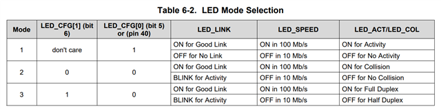
LED CONFIGURATION: This strapping option determines the mode of operation of the LED pins. Default is Mode 1.

Q2

In Table 6-2, it says “On for Good Link”, etc. When “ON”, are the LED_LINK and LED_SPEED pins low or high?

Best Regards,

ttd

  • Hi ttd.

    Does “Default” in 4.8 Strap Options mean without external pull-down resistor?

    If the default option is required, then there is no need for external pullup or pulldown resistors.

    Also, if I want to use Mode 2, should I add a PullDown resistor?

    Please refer to the table below. For Mode 2, it is configured by LED_CNFG bit 1, and LED_CNFG bit 0 or CRS (pin 40). The CRS by default has internal pullup, so you would need to have a 2.2k pulldown to change the CRS to a low condition for Mode 2. 

    In Table 6-2, it says “On for Good Link”, etc. When “ON”, are the LED_LINK and LED_SPEED pins low or high?

    Since these LED pins are also used as strap options, the polarity of the LED is dependent on whether the pin is pulled up or down.

    Specifically, when the LED outputs are used to drive LEDs directly, the active state of each output driver is dependent on the logic level sampled by the corresponding AN input upon power up/reset. For example, if a given AN input is resistively pulled low then the corresponding output will be configured as an active high driver. Conversely, if a given AN input is resistively pulled high, then the corresponding output will be configured as an active low driver.

    Thanks

    David