This thread has been locked.

If you have a related question, please click the "Ask a related question" button in the top right corner. The newly created question will be automatically linked to this question.

AM26C31: output distortion

Part Number: AM26C31
Other Parts Discussed in Thread: TVS0701, TSD12C

Tool/software:

Hi team,

My customer uses a lots of AM26C31IDR in Servo and VFD products.

Now they met a output waveform distortion issue of AM26C31 in servo products, which is that Y ouput or Z output can not be pulled down to GND.

From their end customer’s feedback, issue rate is 20%.

They did the ABA experiments and issue follows with device.

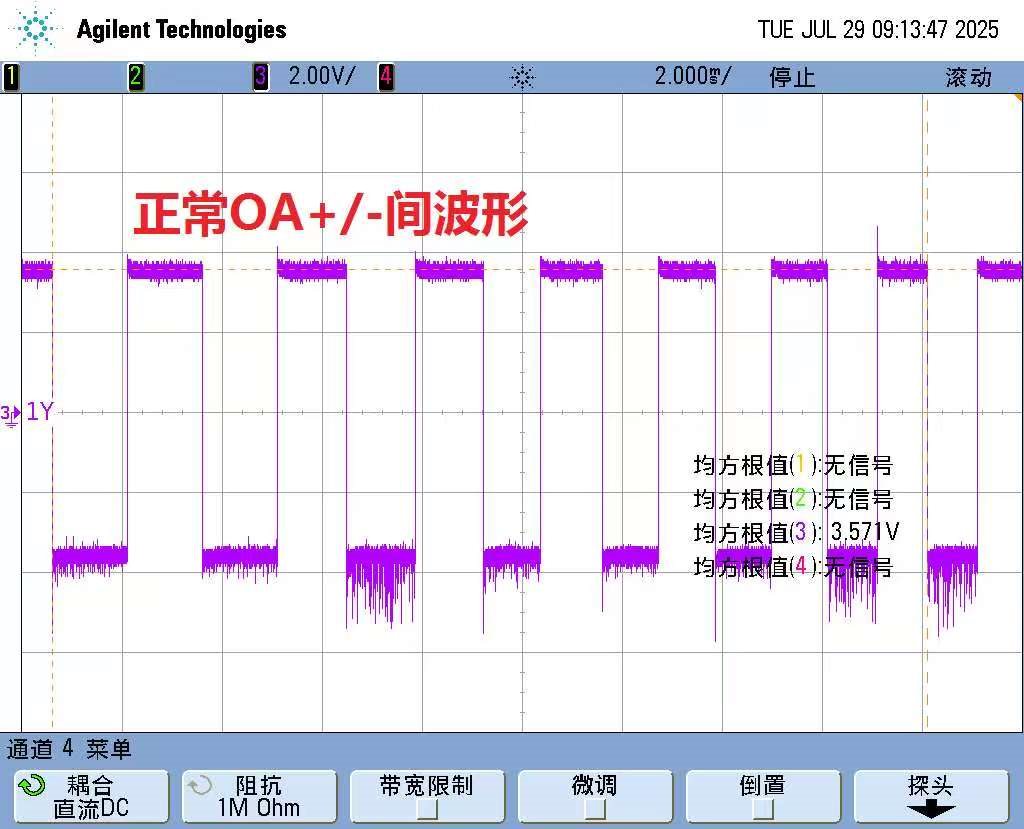
Above is nornal differential siganl from (OA+) - (OA-)

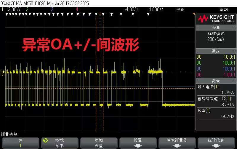
Above is issue waveform and you can see differential signal is nagetive.

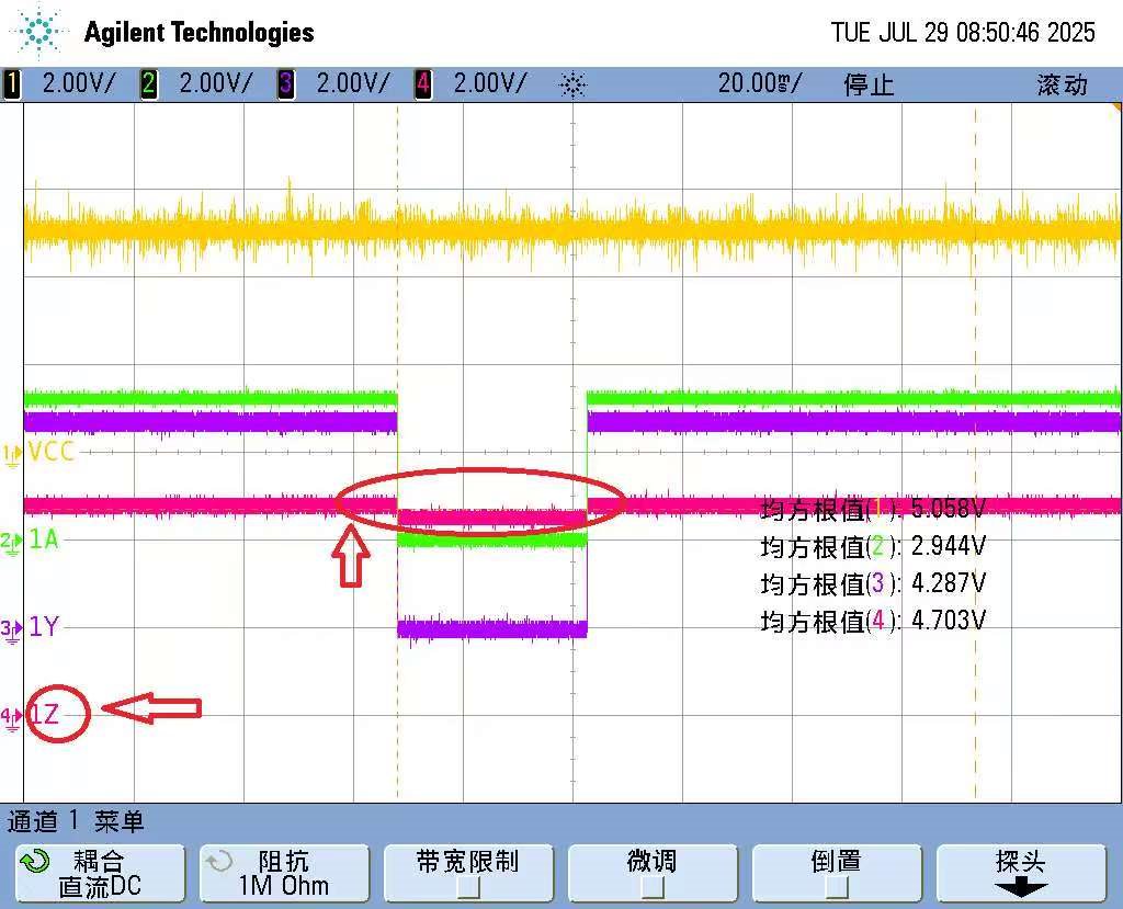
Above figure is to measure 4x signal by using single end to GND. You can see 1Z pin has a abnormal output.

It seems that 1Z can’t be pull down to GND, which means low side MOSFET is damaged or something wrong on MOSFET’s driver.

The TVS device they use between AM26C31’s output and connector is ESDA14V2L, which is 12V/12A/300W. Is it enough for this application?

Could the failure be caused by an ESD problem between those two boards.

Do you think it is suitable to do FA process for this case?

  • The TVS device they use between AM26C31’s output and connector is ESDA14V2L, which is 12V/12A/300W. Is it enough for this application?

    Normally, it's best to use a bi-directional TVS to prevent it from forward biasing if the common mode shifts negative. But in this application and scopeshots, I don't think this is the root cause of the issue.

    Could the failure be caused by an ESD problem between those two boards.

    It's possible damage came from a transient event like ESD. We wouldn't really be able to verify that though.

    Do you think it is suitable to do FA process for this case?

    Can you provide a little more information? 

    When does the device break? (Immediately notice after power up or after some use)

    Is customer performing any kind of stress testing with our devices? If so what?

    Is there any possibility of the device's pins/connector on the Y/Z side being shorted to a power rail during any kind of insertion event?

    -Bobby

  • Hi Bobby,

    Thanks for your quick support.

    When does the device break? (Immediately notice after power up or after some use)

    • It will break when their end customer firstly power it on.

    Is customer performing any kind of stress testing with our devices? If so what?

    • They have no special stress testing on device level. All their testing before out of factory is on product level.

    Is there any possibility of the device's pins/connector on the Y/Z side being shorted to a power rail during any kind of insertion event?

    • As you can see as below, AM26C31's output is on the right and bottom of the connector and this connector has foolproof structure so there is no possible that Y or Z pin will connect with other signal or power supply.

    We want to do FA process. Do you think it is necessary?

  • Hi Gary,

    Sorry I thought I posted a reply to this last week but it didn't go through.

    ...............................................................................................................

    I don't see any issues from the schematic point that would would the output pin like this and it looks like the customer is not using the device outside of recommend operating conditions.

    We want to do FA process. Do you think it is necessary?

    I think it is okay to have our quality team look at this. You can submit a quality return and use this e2e to show that applications team is okay with the submission assuming the quality engineer okays it as well.

    -Bobby

  • Hi Bobby,

    CQE deny to do FA for my customer since issue device is obviously EOS.

    I am asking customer to reproduce the issue by plug in and out for many times and use ESD gun to damage the AM26C31.

    By the way, do you think lower break down voltage bi-directional TVS helpful for this case? Such as TVS0701 or TSD12C

  • By the way, do you think lower break down voltage bi-directional TVS helpful for this case? Such as TVS0701 or TSD12C

    If damage is due to the abs max of our device being exceeded then I believe so. The ESDA14V2Lshows it clamps at around 14.2V while our abs max on the differential pins are 14V. It would be better if you can clamp it sooner. I would also suggest using a bi-directional TVS diode and not a uni-directional. 

    We can loop in the protection devices product line to suggest a TI TVS diode if you'd like.

    -Bobby