


Other Parts Discussed in Thread: THVD1400
Tool/software:
Hi, Sir:
Regarding the THVD1406, I have the following four questions:
The schematic and communication architecture of the THVD1406 are shown in the diagram below.
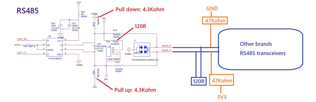
-
I would like to understand why the output voltage levels of the THVD1406 differ depending on whether a 120-ohm termination resistor is present or not.


-
I have measured RS485 transceivers from other brands, and when a 120-ohm termination resistor is applied, both the high and low output voltage levels are significantly offset from the zero level, which seems ideal. How is this achieved? What is the main reason for the voltage level differences compared to the situation described in Question 1?

-
If this difference is due to the choice of transceiver model, what features or specifications should be considered when selecting a transceiver?
-
In cases where the difference is indeed related to the transceiver model, how should a product designer decide between a transceiver that clamps the high-level voltage close to zero and one that maintains both high and low levels at a defined distance from zero?
