Other Parts Discussed in Thread: DP83865
Tool/software:
Dear TI Support Team,
We have migrated from the DP83865 to the DP83867IRPAP due to EOL. The PHY is configured in GMII mode and PHY address is set to 0x01.
In our previous design (with DP83865), we used an LED signal to indicate Ethernet link status, which was connected to our FPGA. When the cable was removed, the system detected it and showed “waiting for Ethernet ready.”
In our new design:
-
We connected LED_2 (pin 61) of DP83867 to the FPGA (named
glink_status). -
LED_2 is not used as a strap.
-
The signal always stays HIGH, even when the Ethernet cable is removed.
-
There is no issue with scan or data communication – we are able to send and receive packets successfully.We would like your help on the following:
-
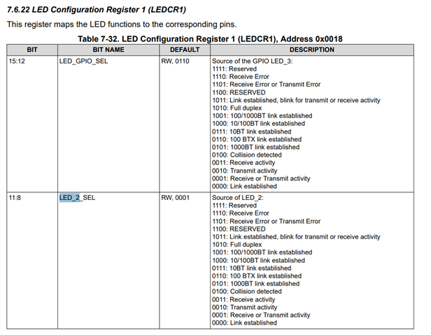
How can we configure LED_2 to indicate link status correctly?
-
Is there any recommended strap or register setting to fix this?
-
Is a pull-down or pull-up resistor required on LED_2 if not used as a strap?
-
Any reference design or application note that shows this setup?
Please guide us on how to make LED_2 work reliably for link detection.
 Existing Design
  current Design schematic
Thanks & Regards,
Pavithran Gunasekaran