This thread has been locked.

If you have a related question, please click the "Ask a related question" button in the top right corner. The newly created question will be automatically linked to this question.

TCAN4550EVM: TCAN4550 MRAM Tx Buffer FIFO/Queue

Part Number: TCAN4550EVM
Other Parts Discussed in Thread: TCAN4550

Tool/software:

I have a question about the TCAN4550EVM.

I'm connecting a Raspberry Pi and a TCAN4550 EVM via an SPI interface.

My goal is to measure the CAN frame data transmitted from the Raspberry Pi through the TCAN4550's CAN Bus DB-9 Wiring Harness Connector.

I've created a program based on the TCAN4550 sample program, intending to transmit data from the TCAN4550's TxBuffer, but haven't been successful.

I can read and write to the TCAN4550 EVM registers from the Raspberry Pi.

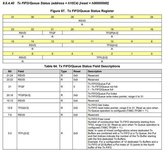
I'm writing to the SPI according to the TCAN4550 software user manual, but I seem to be unable to retrieve the free level from register 0x10C4; the value I'm getting is 0.

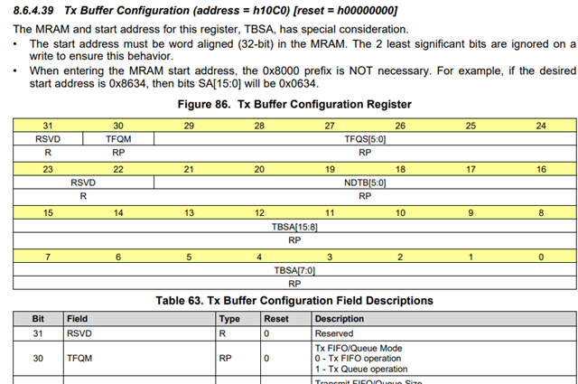
According to the datasheet, this is caused by the Tx being configured as a queue (register TXBC.TFQM = ‘1’).

Reading TXBC using AHB_READ_32() returned 0x4a000174. Since 0x4a000174 indicates TXBC.TFQM=1, I believe the Tx is configured as a queue.

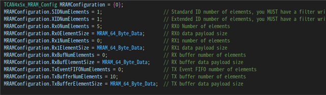
The MRAM configuration appears to be set using TCAN4x5x_MRAM_Configure(), but I couldn't find a way to configure the Tx as a FIFO in the sample program.

How can I configure the Tx to operate as a FIFO?


  • Here are some additional questions.

    I've checked the registers and obtained the following values:

    0x0824: 0x10000000
    0x1044: 0x0000070f

    It appears that an error related to the data phase has occurred.

    If you can determine the cause of this error, I would appreciate your response.

  • Hello Nomura-san,

    You may need to modify the TCAN4x5x_MRAM_Configure() function in the TCAN4550.c file to remove the line setting it to Queue mode by setting the TFQM bit.  By default the device uses FIFO mode.

        // TX Buffer
        MRAMValue = MRAMConfig->TxBufferNumElements;
        if (MRAMValue > 32)
            MRAMValue = 32;
    
    
        registerValue = 0;
        if (MRAMValue > 0)
        {
            registerValue = ((uint32_t)(MRAMValue) << 24) | ((uint32_t)startAddress);
            registerValue |= REG_BITS_MCAN_TXBC_TFQM;               // Sets TFQM to 1 (Queue mode), and sets all registers to be generic non-dedicated buffers.
        }
        startAddress += (((uint32_t)TCAN4x5x_MCAN_TXRXESC_DataByteValue((uint8_t)MRAMConfig->TxBufferElementSize) + 8) * (uint16_t)MRAMValue);
        AHB_WRITE_32(REG_MCAN_TXBC, registerValue);

    Unfortunately the Protocol Status Register resets after it is read and the returned value you shared doesn't appear to be from the first read after the error occurred.  Both the DLEC and LEC values are "7" which means no change since previous read. 

    Generally speaking protocol errors in the data phase come from different bit timing configurations between the nodes on the bus that cause sampling errors.  With CAN FD using Bit Rate Switching, the switch to the faster data bit rate occurs at the sample point in the BRS bit in the message header.  Therefore all devices need to have the same sample point and bit timing configuration so the switch to the faster bit rate occurs on all devices simultaneously.   If any are different, then the devices may sample the bit at different times causing errors.

    You may want to verify the data bit timing settings are the same for all nodes on your bus.

    Regards,

    Jonathan

  • Hello Jonathan,

    Thank you for your answer.

    After disabling the code as you suggested, I confirmed successful transmission.

    Regards,

    Nomura