Tool/software:
I have some questions regarding the design of the AM26C32.
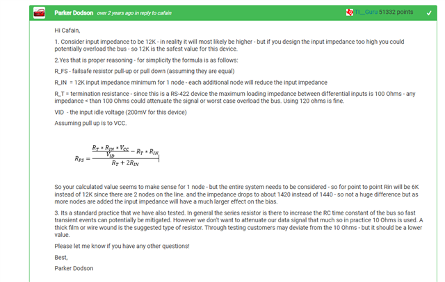
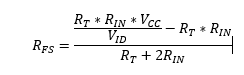
-
I am considering an external fail-safe circuit. I plan to connect Vcc to the positive side and GND with a resistor to the negative side. I intend to calculate the resistor value using the internal pull-up/pull-down resistor of 288kΩ and the input impedance of 12kΩ. What is the tolerance range for the 288kΩ resistor?
-
Is a power-limiting resistor necessary when implementing the fail-safe circuit? If so, what should the resistor value be?
"I would greatly appreciate your response.