This thread has been locked.

If you have a related question, please click the "Ask a related question" button in the top right corner. The newly created question will be automatically linked to this question.

DS90UB941AS-Q1: DS90UB941AS-Q1:Using 941 and 948, in the spiltter mode, how to access the I2C address 948 on port1 via 941

Part Number: DS90UB941AS-Q1

Tool/software:

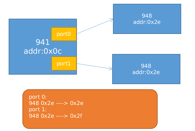
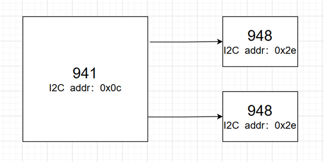
When DS90UB941AS-Q1 is connected to two remote deserializers in splitter or independent mode which have the same physical I2C address, how can they be accessed independently via I2C?

question 1:

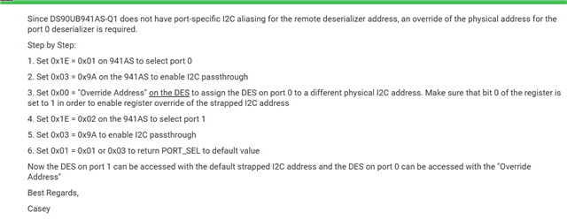
I refer to the following article:

https://e2e.ti.com/support/interface-group/interface/f/interface-forum/1073342/faq-ds90ub941as-q1-access-two-deserializers-in-splitter-mode-which-have-the-same-i2c-address?tisearch=e2e-sitesearch&keymatch=FAQ%25252525252525252520941%25252525252525252520Splitter

it mean that like this?
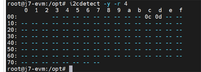
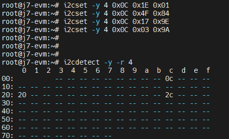
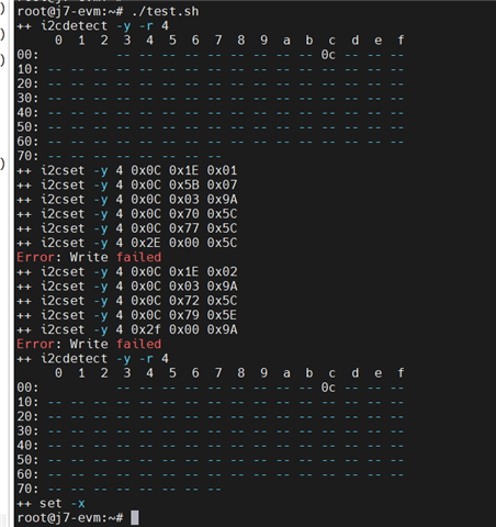
i2cdetect -y -r 4

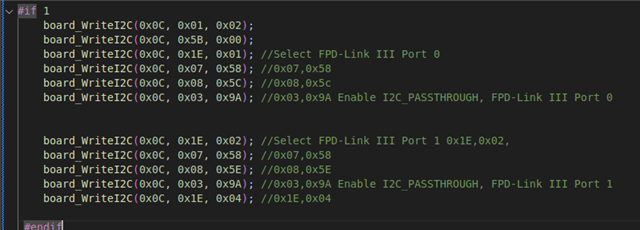
i2cset -y 4 0x0C 0x1E 0x01   # Sel-Port-0

i2cset -y 4 0x0C 0x5B 0x07   # Splitter Mode 0x07

i2cset -y 4 0x0C 0x03 0x9A   # Pass-Through Enabled

i2cset -y 4 0x0C 0x70 0x5C   # 941-Port-0 --- 948(0x2E) # 0x2E<<1  Physical Address

i2cset -y 4 0x0C 0x77 0x5C   # 941-Port-0 --- 948(0x2E) # 0x2E<<1  alias Address

i2cset -y 4 0x2E 0x00 0x5C   #question: this 0x00 it's mean 948 0x00 or 941 0x00?


i2cset -y 4 0x0C 0x1E 0x02    # Sel 941-Port-1

i2cset -y 4 0x0C 0x03 0x9A    # Pass-Through Enabled

i2cset -y 4 0x0C 0x72 0x5C    # 941-Port-0 --- 948(0x2E) # 0x2E<<1  Physical Address

i2cset -y 4 0x0C 0x79 0x5E    # 941-Port-0 --- 948(0x2F) # 0x2F<<1   alias Address

i2cset -y 4 0x2f 0x00 0x9A      #question: this 0x00 it's mean 948 0x00 or 941 0x00?
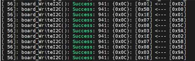
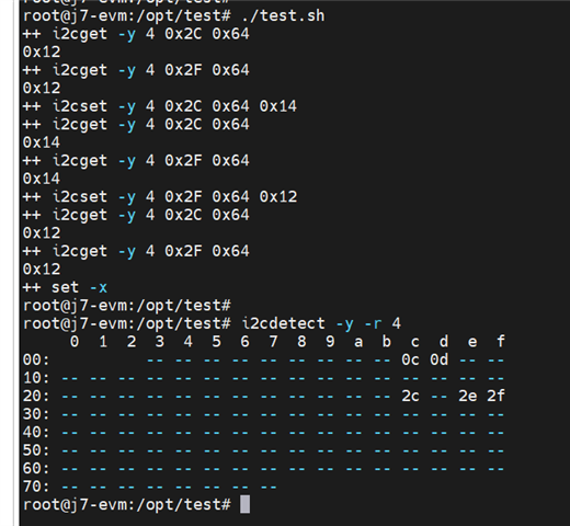
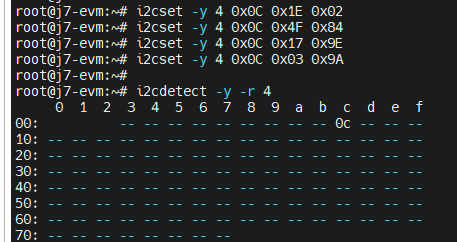
Execution Result:

no devices with addresses 0x2E or 0x2F are detected​ on the bus


Another situation:

#!/bin/sh

set -x

i2cset -y 4 0x0C 0x01 0x08 # RESET


i2cset -y 4 0x0C 0x1E 0x04 # Sel 941-Port-0/1

echo

i2cdetect -y -r 4

echo


i2cget -y 4 0x0C 0x03

i2cset -y 4 0x0C 0x03 0x9A # Pass-Through Enabled

i2cget -y 4 0x0C 0x03


i2cget -y 4 0x0C 0x70

i2cset -y 4 0x0C 0x70 0x5C

i2cget -y 4 0x0C 0x70

i2cget -y 4 0x0C 0x77

i2cset -y 4 0x0C 0x77 0x5D

i2cget -y 4 0x0C 0x77

i2cset -y 4 0x2E 0x00 0x5D


i2cset -y 4 0x0C 0x1E 0x02

i2cset -y 4 0x0C 0x03 0x9A


i2cget -y 4 0x0C 0x72

i2cset -y 4 0x0C 0x72 0x5C

i2cget -y 4 0x0C 0x72

i2cget -y 4 0x0C 0x79

i2cset -y 4 0x0C 0x79 0x5E

i2cdetect -y -r 4

i2cget -y 4 0x0D 0x79

i2cset -y 4 0x2F 0x00 0x5E

echo

i2cdetect -y -r 4


i2cget -y 4 0x2E 0x64

i2cget -y 4 0x2F 0x64

i2cset -y 4 0x2E 0x64 0x14

i2cget -y 4 0x2E 0x64

i2cget -y 4 0x2F 0x64

i2cset -y 4 0x2F 0x64 0x12

i2cget -y 4 0x2F 0x64

i2cget -y 4 0x2E 0x64

set +x

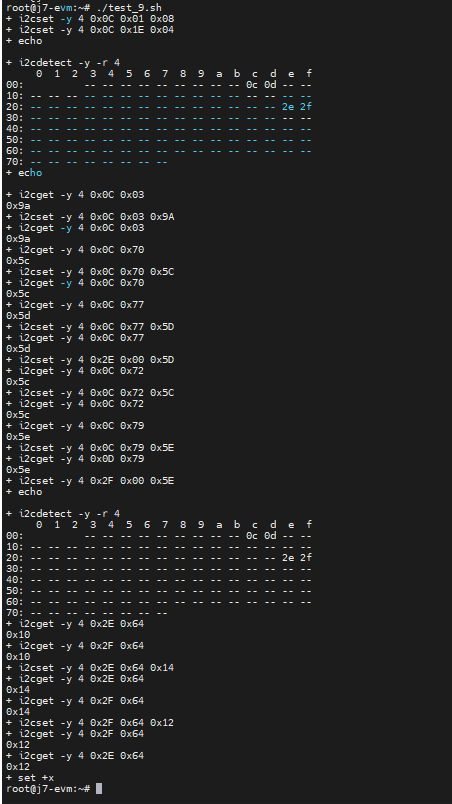
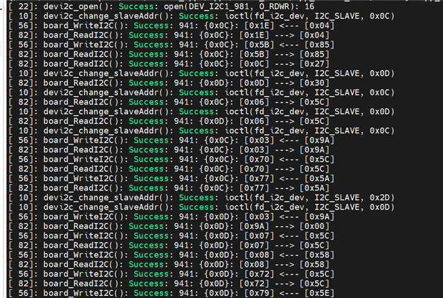
The execution result this time includes addresses 2E and 2F

However, when writing and reading back from the addresses of 2E and 2F in the execution result, it appears to be the same address, both belonging to port0, The address and alias of prot1 are not provided.
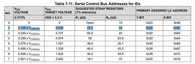
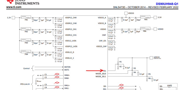
question 2:

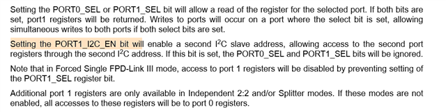
What does this section in the manual actually mean?

question 3:

Can you provide me with a complete example of configuring port 0 and port 1 of 941 to access I2C of 948?

Thanks!

  • Hello,

    Have you tried running this code? What is the Idx strap for each of the DES's you are using for each port ? Do you have both strapped to 0x58 ?

    board.WriteI2C(Ser_addr,0x1E,0x01) #Select FPD-Link III Port 0
    board.WriteI2C(Ser_addr,0x07,0x58) #0x07,0x58
    board.WriteI2C(Ser_addr,0x08,0x5C) #0x08,0x5c
    board.WriteI2C(Ser_addr,0x03,0x9A) #0x03,0x9A Enable I2C_PASSTHROUGH, FPD-Link III Port 0


    board.WriteI2C(Ser_addr,0x1E,0x02) #Select FPD-Link III Port 1 0x1E,0x02,
    board.WriteI2C(Ser_addr,0x07,0x58) #0x07,0x58
    board.WriteI2C(Ser_addr,0x08,0x5E) #0x08,0x5E
    board.WriteI2C(Ser_addr,0x03,0x9A) #0x03,0x9A Enable I2C_PASSTHROUGH, FPD-Link III Port 1
    board.WriteI2C(Ser_addr,0x1E,0x04) #0x1E,0x04

    See example script

    import time
    
    # timing for each panel is 1920*720@60
    # Total Horizontal = '2070'
    # uVisWidth        = '1920'
    # uHsyncFrontPorch = '50'
    # uHsyncWidth      = '50'
    # uHsyncBackPorch  = '50'
    # Total Vertical   = '870'
    # uVisHeight       = '720'
    # uVsyncFrontPorch = '50'
    # uVsyncWidth      = '50'
    # uVsyncBackPorch  = '50'
    # uPixelFreqInHz   = '108054000'
    
    
    Ser_addr = 0x18
    
    board.WriteI2C(Ser_addr,0x01,0x02) # Reset
    
    time.sleep(0.5)
    board.WriteI2C(Ser_addr,0x5B,0x00) #Set 941AS to Auto-Detect FPD-Link III mode (Single, Dual, or Replicate)
    
    board.WriteI2C(Ser_addr,0x1E,0x01)
    board.WriteI2C(Ser_addr,0x66,0x1A)
    board.WriteI2C(Ser_addr,0x67,0x01) #M=1
    board.WriteI2C(Ser_addr,0x66,0x03)
    board.WriteI2C(Ser_addr,0x67,0x02) #N=2
    
    board.WriteI2C(Ser_addr,0x66,0x04)
    board.WriteI2C(Ser_addr,0x67,0x16) #least 8 bit of Total Horizontal frame size
    board.WriteI2C(Ser_addr,0x66,0x05)
    board.WriteI2C(Ser_addr,0x67,0x68) #Least 4 bit TV + Most 4 bit TH
    board.WriteI2C(Ser_addr,0x66,0x06)
    board.WriteI2C(Ser_addr,0x67,0x36) #Most 8 bit of Total Vertical frame size
    
    board.WriteI2C(Ser_addr,0x66,0x07)
    board.WriteI2C(Ser_addr,0x67,0x80) #least 8 bit of active Horizontal frame size
    board.WriteI2C(Ser_addr,0x66,0x08)
    board.WriteI2C(Ser_addr,0x67,0x07) #Least 4 bit AV + Most 4 bit AH
    board.WriteI2C(Ser_addr,0x66,0x09)
    board.WriteI2C(Ser_addr,0x67,0x2D) #Most 8 bit of active Vertical frame size
    
    board.WriteI2C(Ser_addr,0x66,0x0A)
    board.WriteI2C(Ser_addr,0x67,0x32) #Horizontal Sync Width
    board.WriteI2C(Ser_addr,0x66,0x0B)
    board.WriteI2C(Ser_addr,0x67,0x32) #Vertical Sync Width
    board.WriteI2C(Ser_addr,0x66,0x0C)
    board.WriteI2C(Ser_addr,0x67,0x32) #Horizontal back porch
    board.WriteI2C(Ser_addr,0x66,0x0D)
    board.WriteI2C(Ser_addr,0x67,0x32) #Vertical back porch
    board.WriteI2C(Ser_addr,0x65,0x04) #using internal timing and internal clock
    board.WriteI2C(Ser_addr,0x64,0x15) #enable PG/color bars
    
    #0x01,0x00, #enable DSI
    
    board.WriteI2C(Ser_addr,0x1E,0x01) #Select FPD-Link III Port 0
    board.WriteI2C(Ser_addr,0x07,0x58) #0x07,0x58
    board.WriteI2C(Ser_addr,0x08,0x5C) #0x08,0x5c
    board.WriteI2C(Ser_addr,0x03,0x9A) #0x03,0x9A Enable I2C_PASSTHROUGH, FPD-Link III Port 0
    
    
    board.WriteI2C(Ser_addr,0x1E,0x02) #Select FPD-Link III Port 1 0x1E,0x02, 
    board.WriteI2C(Ser_addr,0x07,0x58) #0x07,0x58
    board.WriteI2C(Ser_addr,0x08,0x5E) #0x08,0x5E
    board.WriteI2C(Ser_addr,0x03,0x9A) #0x03,0x9A Enable I2C_PASSTHROUGH, FPD-Link III Port 1
    board.WriteI2C(Ser_addr,0x1E,0x04) #0x1E,0x04


    - Fadi A.

  • hi Fadi,

    thank you for your answer, I have tried the method you provided and the test results are as follows, but I cannot scan the address

    I try run my code:

        board_WriteI2C(0x0C, 0x1E, 0x04); //Select 941-Port-0/1
        board_ReadI2C(0x0C, 0x1E, 0x01);
    
        board_WriteI2C(0x0C, 0x5B, 0x85); // 101 : Forced Independent 2:2 mode
        board_ReadI2C(0x0C, 0x5B, 0x01);
    
        board_ReadI2C(0x0C, 0x0C, 0x01);
        board_ReadI2C(0x0D, 0x0D, 0x01);
    
        board_ReadI2C(0x0C, 0x06, 0x01);
        board_ReadI2C(0x0D, 0x06, 0x01);
    
        board_WriteI2C(0x0C, 0x03, 0x9A); //
        board_ReadI2C(0x0C, 0x03, 0x01);
    
        board_WriteI2C(0x0C, 0x70, 0x5C); //0x07,0x58
        board_ReadI2C(0x0C, 0x70, 0x01);
        board_WriteI2C(0x0C, 0x77, 0x5A); //0x08,0x5c
        board_ReadI2C(0x0C, 0x77, 0x01);
    
        board_ReadI2C(0x2D, 0x00, 0x01);
    
        board_WriteI2C(0x0D, 0x03, 0x9A); //
        board_ReadI2C(0x0D, 0x9A, 0x01);
    
        board_WriteI2C(0x0D, 0x07, 0x5C); //0x07,0x58
        board_ReadI2C(0x0D, 0x07, 0x01);
        board_WriteI2C(0x0D, 0x08, 0x58); //0x08,0x5c
        board_ReadI2C(0x0D, 0x08, 0x01);
    
        board_WriteI2C(0x0D, 0x72, 0x5C); //0x07,0x58
        board_ReadI2C(0x0D, 0x72, 0x01);
        board_WriteI2C(0x0D, 0x79, 0x5E); //0x08,0x5c
        board_ReadI2C(0x0D, 0x79, 0x01);
        board_ReadI2C(0x2F, 0x00, 0x00);

    The running result is as follows:

    But when reading and writing, it still appears to be reading and writing to the same address.

  • Hi Lin,

    Let me get some hardware setup on my bench with this configuration to test the code on my end to see if similar observation - let's target 1-2 business days I will test and get back to you by Wednesday 8/13

    - Fadi A.

  • Hi Fadi A,

    I'm looking forward to your reply. And I conducted more tests to verify this issue, I tried to change the I2C address of one of the 948 on the hardware, from 0x2E to 0x2C, but the problem still exists.

    Because in terms of hardware, 948 is the same address 0x2E, so we hope to achieve the following goals while keeping the original I2C address unchanged:

    Thank!

  • Hey Lin,

    Can you confirm what is the IDx Pin47 strap set to with the external voltage divider network on each of these 948 displays? 

    Are both displays strapped to mode#1? Can you send over the schematic for those displays please. 

    - Fadi A.

  • hi Fadi A,

    here is the schematic:

    Yesterday I say that change the I2C address of one of the 948 on the hardware, from 0x2E to 0x2C. And i find out in our board, use FPD-LINK, only port 0 can find the i2c address when use pass through.I think this may be our problem, why can't Port1 find the address.

    i2cset -y 4 0x0C 0x1E 0x01
    i2cset -y 4 0x0C 0x4F 0x84
    i2cset -y 4 0x0C 0x17 0x9E
    i2cset -y 4 0x0C 0x03 0x9A

    port 1 can not find the i2c address.

    i2cset -y 4 0x0C 0x1E 0x02
    i2cset -y 4 0x0C 0x4F 0x84
    i2cset -y 4 0x0C 0x17 0x9E
    i2cset -y 4 0x0C 0x03 0x9A

    Best Regards,

    Lin

  • thank you Fadi A, This issue has been resolved, and this is our configuration. I hope it can help others who encounter similar problems, 

    ===================================================================

    #!/bin/sh
    set -x

    ##############################################################
    # 941-Port-0-948: 0x2E->2A
    # 941-Port-1-948: 0x2E->2F
    # enable I2C Pass-Through
    ##############################################################
    trap 'sleep 0.5' DEBUG

    #i2cset -y 4 0x0C 0x01 0x02 # Resets the entire digital block including registers
    sleep 1

    i2cset -y 4 0x0C 0x1E 0x04 # Sel port0 port1 both port sel
    #i2cset -y 4 0x0C 0x5B 0x87 # Coax # 111 : Forced Splitter Mode # PSR(port share register)
    i2cset -y 4 0x0C 0x4F 0x84 # if display configuration is run,this line not run
    #i2cset -y 4 0x0C 0x5B 0x07
    #i2cset -y 4 0x0C 0x56 0x80
    sleep 1

    i2cget -y 4 0x0C 0x0C # 941-Port-0: 0'b : LINK_DETECT
    i2cget -y 4 0x0C 0x06 # 941-Port-0: 7-bit Deserializer Device ID

    #i2cset -y 4 0x0C 0x17 0x9E # I2C_PASS_ALL

    i2cset -y 4 0x0C 0x03 0x9A # Pass-Through Enabled
    i2cget -y 4 0x0C 0x03
    i2cset -y 4 0x0C 0x70 0x40 # phy touch pad 0X20
    i2cset -y 4 0x0C 0x77 0x40 # alias touch pad 0X20
    i2cset -y 4 0x0C 0x07 0x5C # 0X2E
    i2cset -y 4 0x0C 0x08 0x5A # 0X2D

    i2cget -y 4 0x0D 0x0C # 941-Port-1: 0'b : LINK_DETECT
    i2cget -y 4 0x0D 0x06 # 941-Port-1: 7-bit Deserializer Device ID

    #i2cset -y 4 0x0D 0x17 0x9E # I2C_PASS_ALL

    i2cset -y 4 0x0D 0x03 0x9A # Pass-Through Enabled
    i2cget -y 4 0x0D 0x03
    i2cset -y 4 0x0D 0x07 0x5C # 0X2c
    i2cset -y 4 0x0D 0x08 0x5E # 0X2f

    sleep 1
    #i2cdetect -y -r 4

    i2cget -y 4 0x2D 0x00 # read 948-ID
    i2cget -y 4 0x2F 0x00 # read 948-ID

    i2cget -y 4 0x2D 0x64
    i2cset -y 4 0x2D 0x64 0x14
    i2cget -y 4 0x2D 0x64
    i2cget -y 4 0x2F 0x64
    i2cset -y 4 0x2F 0x64 0x12
    i2cget -y 4 0x2F 0x64
    i2cget -y 4 0x2D 0x64

    #i2cdetect -y -r 4


    set -x

    ===========================================

    Best Regards,

    Lin