TUSB1104: SLS Debug

Part Number: TUSB1104


Tool/software:

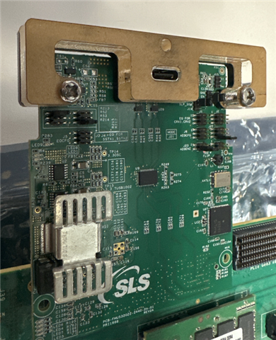
I have programmed the Altera board with the .jic file

Specifically with:

 https://e2e.ti.com/cfs-file/__key/communityserver-discussions-components-files/138/usb32dc_5F00_a10socdb_5F00_fmcusb32g22_5F00_con1_5F00_lane1_5F00_i2c.jic

I still cannot get enumeration to happen on our host PC.

  • Hi Vishesh,

    We are not using any PHY chip for device design. Instead, we are using Transceiver IP core inside FPGA chip. So differential TX & RX pins are exported from FPGA.

  • Understood. This is proving difficult to isolate the issue. I do not see any major differences that would explain the gap in performance between lane1 and lane2 on the daughtercard, FPGA, or the host side. My next question would be the EQ capability of the FPGA device. Does lane1 and lane 2 have the same EQ capability? 

    As we know in a linear redriver system EQ can only be provided on the redriver. Due to this limitation we must rely on the host and device EQ to compensate for what the redriver cannot. We can see this in the below diagram.

    We know that the TUSB1104 can operate within a compliant USB system as we have passed compliance testing with this part. We need to delve deeper into the system itself to debug why one lane is working and the other isn't. 

  • Hi Quick update. 

    I tried testing you system with a standard USB RX Jtol test for a USB device, but the FPGA does not go into loopback mode. This test would provide insight into what the USB3.2 waveforms coming out of the FPGA system look like. However, this test does work well with your system as we need to send the command over the USB Type-C connection to start loopback mode.

    I have both lane1 and lane 2 as stable as possible for the GPIO modes. Iwas able to do this by making the daughtercard and FPGA connect more solidly by providing more support to the daughtercard.  

    Lane 1 has no errors for test >30mins long. 

    Lane 2 has no errors for test >10 mins long, but occasionally has 1 or 2 recoverable errors in longer tests.

    This should mean that when using USB3.2 gen 2x2 we should see a few errors but the link should still operate. However, when using in 20Gbps mode the link fails almost immediately. 

    The links individually working, but not working when used together imply a possibility of crosstalk being the culprit. We have had issues in the past where socket connector have poor crosstalk performance. I am looking further into this option.

    Do you have any s4p files for the connect used here? Additionally are you able to reduce the amplitude of the USB signal from the SoC to see if this affect the SI at all?

  • [Vishesh]: next question would be the EQ capability of the FPGA device. Does lane1 and lane 2 have the same EQ capability? 

    [SLS]: Yes

  • Hi vishesh,

    Thanks for update and your continuous support,

    Here are some queries regarding testing:

    1)Have you changed default Pin-Strap Mode setting which we have fixed while supplying cards?

    2)Have you got success with I2C mode to configure Redriver setting? 

    3)Have you got success with Loopback mode testing based on below abstract of your feedback? Please provide more details.

    4)Have you got below improved performance by changing any Pin-Strap Mode setting Or I2C Based redriver setting of AEQ Or by pressing Daughter Card to make solid connection with FPGA Motherboard.


    5)Requirement of S4P Touchstone file is for USB Type-C Connector Or FMC Connector?

    Kindly provide your valuable feedback. We are planning to do conference call meeting with you at 9:00 AM CST time.

  • 1)Have you changed default Pin-Strap Mode setting which we have fixed while supplying cards?

    I dont recall what the default pin-strap configuration is. This is the current config.

    2) Yes, I have a PC which is able to program via I2C, but I am unable to get the I2C board to enumerate.

    3) I have tried this testing, but the FPGA is unable to get into loopback mode here. I am debugging this currently.

    4)Have you got below improved performance by changing any Pin-Strap Mode setting Or I2C Based redriver setting of AEQ Or by pressing Daughter Card to make solid connection with FPGA Motherboard.

    The pin-strap configuration is shown above, I notice that slight changes in the angle of the Daughtercard connector leads to performance differences in the USB validator GUI I am testing with. 

    5)Requirement of S4P Touchstone file is for USB Type-C Connector Or FMC Connector?

    Id like the S4P file to have a better understanding of the FMC connector.

    Kindly provide your valuable feedback. We are planning to do conference call meeting with you at 9:00 AM CST time.

    I have a meeting at this time on Friday. Can we try Monday next week at 9:00am?

  • Hi Vishesh,

    Thank you for the update.

    Please find the FMC Connector S4P Touchstone files at the following OneDrive link:

    [FMUS32G22]

  • Hi,

    Thanks, I will review it. 

  • Hi Vishesh, I’ve generated the meeting link for 9:00 AM CST, which is 7:30 PM IST.

    Please find meeting link for same:

    teams.microsoft.com/.../0

  • Hi,

    Thanks for the meeting. Please send the instructions for TX and RX testing of the USB port here with the test procedure to put the system into compliance mode. 

  • Hi Vishesh,

    I have uploaded Lane1 Gen2 mode sof file at TX_RX_Compliance_testing

    Here A10 FPGA is not able to detect ping lfps sent by scop(Tx compliance tester)e hence used user_pb_fpga1 push button in A10SOC board.

    When Scope(Tx compliance tester) ask to next pattern then you need to manually press this push button to increment pattern form device.

    Here I have shared signal tap file which used to trace which compliance pattern number is transmitted by device

    Also shared image and script for TX compliance test.

    Tomorrow I will share Tx compliance mode sof file for lane2 and Gen2x2.

    Once you test, I will share sof files for RX compliance. 

  • Hi,

    Thanks for this, I will try testing this today. If i have any issues I will let you know.

  • Hi,

    I have uploaded Lane2 Gen2 mode sof and gen2x2 sof for TX compliance testing as same location.

    You can use same signal tap file for all three sof to trace which compliance pattern number is transmitted by device

  • Hi,

    Sorry for the delays. It took some time getting the setup working. However, I am able to test the TX eye diagrams now!

    Thanks for the help. I have noticed that we fail the short channel template test as the eye diagram exceeding the maximum output swing. 

    Were we aware of this?

    We do pass long channel eye diagram testing on lane 1 with no issue. I will test lane2 and 2x2 tomorrow.

  • Hi Vishesh,

    I have uploaded three bit stream file for RX compliance test. 

    RX_compliance

  • Perfect, thanks.

    As of right now the TX eye diagram looks the same for con1_lane1, con1_lane2, and gen 2x2. Wes till see the same issue of too wide of an eye diagram for the short channel across all 3 tests, but the rest of the test pass across the board.

  • Dear Vishesh, It was very nice and informative meeting session with you on last Monday.

    Thank you so much for your continuous support. As discussed can you please share list of equipments available in TI LAB which can be used for High Speed Signal Integrity Characterization ? Also share available 4-Port VNA Model Number.

    Is anyone from below Teledyne Equipment available in TI LAB?

    We will back after Diwali Holidays (3rd November-2025).

    Happy Diwali and Prosperous New Year to you and your family.

  • Hi Nilay,

    Sounds good. I will check on equipment and get back to you.

    Additionally I have the TX test reports for your reference.

    https://e2e.ti.com/cfs-file/__key/communityserver-discussions-components-files/138/con1_5F00_lane2_5F00_TX_5F00_Eye_5F00_Diagram.mht

    https://e2e.ti.com/cfs-file/__key/communityserver-discussions-components-files/138/con1_5F00_lane1_5F00_TX_5F00_Eye_5F00_Diagram.mht

    https://e2e.ti.com/cfs-file/__key/communityserver-discussions-components-files/138/Gen2x2_5F00_TX_5F00_Eye_5F00_Diagram.mht

    Happy Diwali!

  • Hi,

    I have tried getting 5G Rx compliance to work, but the system cannot get into loopback mode. I am using the script file provided, and the setup is the same as the diagram. I am using a M8020 BERT rather than a M8040. Do we have an SOF file for RX compliance mode as well?