TUSB1104: reverse plugging not working

Part Number: TUSB1104
Other Parts Discussed in Thread: TUSB321, TUSB1044, TUSB1042I, TUSB321AI

Tool/software:

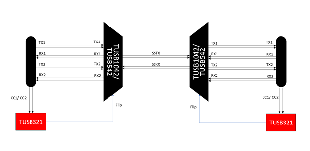
We are testing a custom PCB with TUSB1104 re-driver. We have receptacle on both side of the TUSB1104. Below are the configurations 

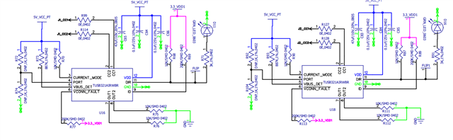
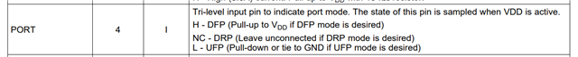
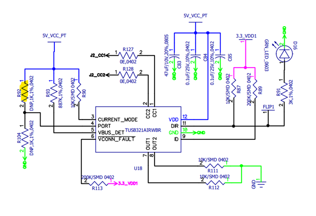
1) CC1 & CC2 of input side (for host) receptacle is pulled low. CC1 & CC2 of output side (device) receptacle is controlled through TUSB321. TUSB321 is configured as DFP. 

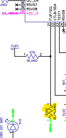
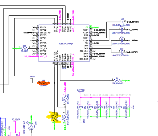
2) FLIP pin - TUSB321 is controlling FLIP PIN. Also tried manual switch for FLIP between 3.3V and ground. 

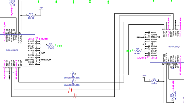
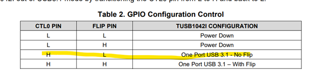
3) Configured as PIN strap mode (not in I2C mode) . 

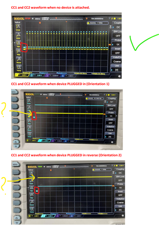
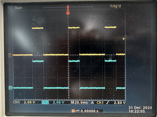
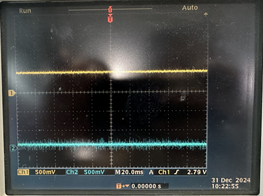
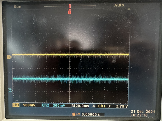
Board is working in one particular orientation of cable. But if we reverse plug in cable on either side of the board, it stops working but if we reverse the second side cable as well then it will work. Suggest possible causes. 

  • Hi,

    Can you share a schematic of the system?

  • If possible try holding the flip pin low. And test using this configuration.

    • We have tested with flip pin manually connecting between 3.3V and ground and it didn't help. Also note that TUSB321 Output is changing HIGH/ LOW based on orientation. I have attached the schematics for your reference.
    •  6472.TUSB1104.pdf
  • Hi Justin,

    As the TUSB1104 does not have a crossbar mux built in, so It is not able to route flipped signals to the appropriate location. For the application you are looking to use, design will need to be as follows. This will allow for all orientations of USB-C cables to work. Y

    ou can keep the current design if you are able to fix the orientations of cables.

  • Hi ,

    Thank you, this helped to understand. I have two more related questions

    1) Does single TUSB1044 & TUSB321 combination solves our issue? We noticed TUSB1044 have internal mux and redriver. I am trying to avoid usage of two redriver IC.

    2) If we keep device side USBC cable connection fixed and only allow host side USBC flipping, is there a simpler solution?

    Thanks in advance. 

  • Hi Justin,

    The TUSB1044 does not have a crossbar MUX built in. It only has an AUX -> SBU mux.

    If you are able to fix the orientation of one cable you can get away with using only one MUX rather than two.

  • Hi Vishesh Pithadiya,

    Thanks. While using TUSB1042I, in the design block diagram you have shared we could see TX is connected to TX and RX to RX. Do we need TX to RX inversion? We will be using USBC receptacle on either side. 

    Also, as per TUSB1042I datasheet SSTX and SSRX are for upstream facing port. In above diagram for the first TUSB1042I IC TX/RX is connected to the receptacle. Does this configuration work seamlessly? 

    Do we need R-ESD series resistor on the superspeed lines for ESD compliance? Can it be added on the host facing superspeed lines? 

    As per application diagram of TUSB1042I, 0.1uF is recommended on Tx line. Do we need to add any CAP on Rx line? Do we need capacitor on super speed lines between TUSB1042I?

  • Hi,

    Thanks. While using TUSB1042I, in the design block diagram you have shared we could see TX is connected to TX and RX to RX. Do we need TX to RX inversion? We will be using USBC receptacle on either side. 

    The naming convention and data direction for a USB Type-C can be seen below:

    Also, as per TUSB1042I datasheet SSTX and SSRX are for upstream facing port. In above diagram for the first TUSB1042I IC TX/RX is connected to the receptacle. Does this configuration work seamlessly? 

    The TUSB1042 can be used in MUX and DEMUX applications. The EQ will be applied appropriately in both directions:

    The type-C end of the MUX will work seamlessly, but we will need to careful on the common side of the MUX. The data directions can be seen in the highlights. We need to make sure this is consistent with the USB-C receptacle at the common side.

    Do we need R-ESD series resistor on the superspeed lines for ESD compliance? Can it be added on the host facing superspeed lines? 

    This depends on the customer requirement for ESD. We have use the PUSB3FR4 successfully in the past.

    As per application diagram of TUSB1042I, 0.1uF is recommended on Tx line. Do we need to add any CAP on Rx line? Do we need capacitor on super speed lines between TUSB1042I?

    We recommend having 100-220nF on the TX pins and 330nF on the RX pins. The RX capacitors are optional.

    Please share an updated schematic so I can review before going into layout/ fab.

  • Hi Vishesh Pithadiya,

    Thanks for the detailed response. Please find the updated schematics and pin mapping image for your reference. Please do review and let us know your suggestions.

    TUSB1042 redriver for type c application.pdf

  • Hi,

    I will review this and get back to you by Friday. I want to make sure we do everything correctly, so I will sped some extra time on this one.

  • Hi Vishesh Pithadiya,

    Let us know if you could review and if there are any comments on the schematics. Thanks. 

  • Hi Justin,

    Sorry for the delays. Here is the schematic review:

    1) Chnage the 100nF caps here to 330nF for the RX pins. Make sure the CMC has sufficient BW for USB 3.2 Gen 2.

    2) Need Ac coupling on the common RX path as well.

    3) Best to to have 100nF on TX lines and 330nF on the RX lines. 

    4) Having the TUSB321 as DRP is correct. Flip pin is also routed correctly. 

    5) Make sure LDO is sufficiently rated for Downstream Vbus as well.

  • Hi Vishesh Pithadiya,

    We have designed and tested above schematics. But unfortunately, USB3 enumeration is not at all working. Are there any specific check points or configurations we need to verify? 

    Are we correct in connecting TX to RX and vice versa on the first receptacle (cable connecting to host)?

    Also, SSTX pins of both IC have connected each other. In EVAL board and every other application circuit we could see SSTX connected to host side? Can you check this once again? 

  • Hi Justin,

    Are you able to measure USB waveforms going into and out of the the board?

    Are you able to remove the CMC and replace with a short for testing?

  • Looking at the schematic, the signal may be overcompensated due to the EQ settings. 

    I would debug using the following steps:

    1) Use a continuity test to make make sure the muxes are routed correctly.

    2) Check that Vbus is being applied to the output correctly.

    3) measure input and output eye waveforms to see if there are any signal quality issues.

    4) Tune EQ to be lower to see if we see improvements in the eye waveform.

    5) Test with USB protocol analyzer to see where in enumeration the system fails.

  • Hi Vishesh Pithadiya,

    Thanks for your detailed debug steps. We could resolve the detection issue with following correction.

    1) Unlike TUSB1104, for TUSB1042I we have connected TX to TX and Rx to Rx without crossover.

    2) SSTX from 1st TUSB1042I IC we have connected to SSRX of 2nd TUSB1042I and vice versa. 

    Both changes helped and we are able to FLIP the USB C cable on the host side. FLIP logic on the secondary (device) side is still not working (TUSB321 output is always HIGH). We have tested secondary TUSB321 in both DRP and DFP mode. Do you have any further suggestions?

    And unfortunately, we do not have high speed oscilloscope/usb analyzer right now for verifying eye diagram or enumeration. 

  • Both changes helped and we are able to FLIP the USB C cable on the host side. FLIP logic on the secondary (device) side is still not working (TUSB321 output is always HIGH). We have tested secondary TUSB321 in both DRP and DFP mode. Do you have any further suggestions?

    Hmm, that's odd. It looks like you have already swapped out the TUSB321 and had the same results.

    And unfortunately, we do not have high speed oscilloscope/usb analyzer right now for verifying eye diagram or enumeration. 

    I understand you do not have access to a high seed scope, but do you have access to one with approx. 200MHz BW? Lower BW may work as well.

    If you do can you probe the CC1 and CC2 inputs of the TUSB321 that always has a high output. Id like to see the waveforms with and without a cable connected. 

  • Which CC controller is having issues U16 or U18?

  • Yes we have 200MHz. We will monitor CC1 and CC2 pin and share you the details.

    U16 is working perfectly whereas U18 is having the issue.

  • Got it, Ill have another look at the schematic. Send the data once you have it ready. Thanks!

  • The schematics look the same to me, so I dont see why one works and the other doesn't. Try depopulating R109 here.

    Did you get the chance to capture the CC waveforms?

  • Hi Vishesh Pithadiya,

    R109 is not assembled in our PCB. We tried to bring up second PCB with same changes but unfortunately, we USB enumeration is still not working. We are figuring out what's the issue. Once this PCB is up and running (first PCB we had to give to another team for continuing rest of the development), we will be able to provide CC waveforms. 

    Meanwhile we have a doubt on CC configuration of device side. 

    The J1 USB receptacle is connected to the host laptop, and the TUSB321AI IC is used to pull down the appropriate CC pins to enable the FLIP logic functionality. The J2 USB receptacle is intended for connecting USB devices (e.g., a pen drive), where the device side is expected to pull up the CC pin, and the internal logic of the USB device (such as the pen drive) should pull down the corresponding CC pin.

    Is this the correct implementation approach? Specifically, is it appropriate to use the TUSB321AI IC to pull down the CC pin on the device (J2) side as well, or should the device handle that internally?

  • Hi Justin,

    The PUP and PDOWN circuitry for the CC lines is handled within the CC controller. I recommend keeping the CC controller in DRP mode allowing for the port to enumerate as either DFP or UFP to increase flexibility. 

    From my understanding, this board is reversible. 

    J1 -> Host

    J2 -> Device

    Can we try

    J1 -> device

    J2 -> Host?

    We can see if this is a device side issue or a CC controller issue.

  • Hi Vishesh Pithadiya,

    Got it Thanks. We have added an efuse on VBUS from J1 as a protection on our final schematics (merged with other requirements). Hence, we will not be able to reverse currently. But will try to test this option as well. 

  • Ok, sounds good.

    Let me know when we have some data available.

  • Hi Vishesh Pithadiya,

    We captured CC1 & CC2 of J2 connector. Please find the attachment for waveforms, when no device attached and with device attachment in both orientation.

    Waveforms.pdf

  • Hi,

    Thanks for the waveforms. From what I see the waveforms looks correct when no device is plugged in. However, I'm not able to see what the voltage levels of  CC1 are as ground reference is not present in the scope captures.

  • I will take some captures using our TUSB321 EVM in lab and post them here for reference.

  • Sure. CC1 and CC2 are toggling between 5V and 1.8V. 

  • Here are the waveforms i captured:

    1) No device plugged in

    2) Normal Orientation

    3) flipped orientation:

    Looks like the values for CC are too high in your system. Is it possible that this part was damaged?

  • Hi Vishesh Pithadiya,

    We've measured the CC1 and CC2 waveforms on the host side — both lines are toggling correctly between 0V and 1V depending on cable orientation, so the FLIP logic appears to be working as expected on this side.

    However, on the device side, CC1 and CC2 are toggling between 5V and 1.8V across multiple boards. Just to observe, we swapped the host USB to the original device side connector, and in this setup, both CC1 and CC2 lines toggle correctly between 0V and 1V based on cable orientation. 

    Could there be an issue with the TUSB321 configuration on the device side?


  • What is the device used in this application? 

    If we are able to detect the host correctly on both the host connector and device connector on our board the issue may be with the device used. Have we tried multiple devices here to see if the issue is consistent?

  • Hi Vishesh Pithadiya,

    We are using a USB3 camera as device. We have also tested it USBC pen drive. Each behavior is the same.  

    We are able to get identical waveforms for CC1 & CC2 on both end if we connect it to host laptop. But if we use J2 receptacle as host, USB enumeration is not working. 

  • What is the sequence of connections you are using?

    1) Try plugging in device to custom board, then plugging in custom board to host.

    2) Try plugging in host to custom board and then plug in device to custom board.

    I see that ESD diodes are only implemented on the host side, but not on the device side. Are we sure no ESD damage has taken place?

    What we can try is manually pulling down the FLIP pin on U15 so we will remain in normal orientation 

    For this we will need to depopulate R78 and repopulate R109

    Then try both orientations of the device on the connector and see if we can enumerate. 

    The CC waveforms seem incorrect, but as the port works with the host and not the device this is odd. One thing we can try is setting U18 as DFP rather than DRP forces this to be a downstream facing port. 

    This is done by PUP the PORT pin

    Try measuring the CC waveforms after changing this.

  • We tried both connection sequences:

    1. Plugging the device into the custom board first, then connecting the custom board to the host.

    2. Plugging the host into the custom board first, then connecting the device.

    There was no difference in behavior in either case. However, when we manually pull down the FLIP pin on the TUSB1042I, the setup works correctly, and the signal routing is as expected. This suggests that orientation detection may not be functioning properly under normal conditions.

    We conducted below experiments to evaluate the behavior of the CC1/CC2 lines under different configurations.

    EXP 1 – Flip Pin Pulled Down (R78 depopulated, R109 - 1K mounted) + DRP Mode

    USB Camera Cable: Orientation 2
    J2_CC1 (across R83): 1.8V
    J2_CC2 (across R84): 4.8V
    Signal: Superspeed 


    USB Camera Cable: Orientation 1
    J2_CC1 (across R83): 4.6V
    J2_CC2 (across R84): 1.8V
    Signal: No super speed

     EXP 2 – Flip Pin Pulled Down (same as above) + DFP Mode Enabled 

    Camera Cable: Orientation 2
    J2_CC1 (across R83): 1.8V
    J2_CC2 (across R84): 4.8V
    Signal: Superspeed 


    Camera Cable: Orientation 1
    J2_CC1 (across R83): 4.6V
    J2_CC2 (across R84): 1.8V
    Signal: No super speed

     EXP 3 – Flip connected to TUSB321 IC + DFP Mode Enabled 

    Camera Cable: Orientation 2
    J2_CC1 (across R83): 4.6V
    J2_CC2 (across R84): 1.8V
    Signal: No super speed


    Camera Cable: Orientation 1
    J2_CC1 (across R83): 1.8V
    J2_CC2 (across R84): 4.8V
    Signal: Superspeed 

  • Hi,

    Thanks for confirming. Yes, looks like this issue is stemming from incorrect settings of the FLIP pin. Now as we have confirmed that the routing can operate correctly. We will dig deeper into the CC controller as this seems to be the root cause. 

    Now that the CC controller is disconnected from the FLIP pin of the TUSB1042, are we able to probe the DIR pin of the CC controller and make sure the setting is accurate for normal and flip orientations as per the datasheet. 

    Additionally where are you probing the CC voltages. These values seem to high.

    These are the detecting tolerances for reference.

    CC1 is used for normal orientation and CC2 is used for flip orientation.

    When we see CC1 at 1.8V this means that a 5V 3A connection should take place, and this is what we see in all the experiments. However, the unused CC lines should be pulled down to ground when this takes place.

    Can you measure the CC voltages on U18 and U16 and see if the CC waveforms are as expected on U16?

  • Hi Vishesh Pithadiya,

    Yes, it is due to incorrect FLIP output from TUSB321AI IC. Like you said the voltage output is not as expected. 

    CC voltage waveform is fine for U16 (toggling correctly between 0V and 1V depending on cable orientation) whereas U18 output is not of same as i mentioned earlier. We have measured this on R127, R128 resistor. But not sure what's the cause!