This thread has been locked.

If you have a related question, please click the "Ask a related question" button in the top right corner. The newly created question will be automatically linked to this question.

TCA9555: for LED application

Part Number: TCA9555
Other Parts Discussed in Thread: PCF8574A, PCF8575, PCF8574, TCA9554, PCA9555, PCA9554, PCA9554A, TCA9554A, TCA9535

Tool/software:

Hi Sir,

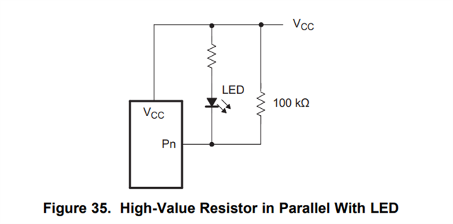
we use the TCA9555 design for LED application, there any issue with this schematic as below? could help double check it for us? thanks for your help and learn from you.

TCA9555 for LED_20250814.pdf

  • Hi Tommy,

    TCA9555 IOL sinking current capability is up to 25 mA, with continuous abs. max current through ICC up to 160 mA. 

    Current mA budget is 12 x 2.3 = 27.6 mA of LED current which TCA9555 can handle. 

    IO Expander Checklist


    Check

    Status (good, okay, verify?)

    Comment

    Local Decoupling Capacitors

     Good

    Generally, a 0.1-uF capacitor is placed on VCC, as close to the device as possible

    C137 - 4.7 uF, 6.3V

    Verify the schematic pinout matches the data sheet pinout

     Good

    Sometimes leaded and non-leaded package variants pinouts get mixed up

    Check that the pullup resistors are present on the SDA and SCL net within the schematic.

     Verify

    Not on current schematic page, but I believe PU resistors are most likely provided on page 4, 7, 9, 11 in the rest of the schematic. 

    Unused GPIO pins configured as INPUT’s are biased to either VCC or GND via resistor

     Good

    Most of TI's IO expander portfolio do not include internal pull-up resistors on the p-port pins; the exceptions are PCF8575, PCF8574, PCF8574A, TCA9555|PCA9555, PCA9554|TCA9554, and TCA9554A|PCA9554A and therefore can be left floating.


    An alternative approach is after powering up the device, any unused p-port pins can be set as an output (does not matter if set high or low).


    TCAL agile IO expanders also have the ability to enable internal PU or PD resistors.

    The LED implementations on the Pxx pins use 100k external PU resistors to LED_VCC (i.e. R113). This will sink unnecessary current. 

    TCA9555 already has internal 100k PU resistors built in on each I/O, see functional diagram below. 

    Device address is unique on the bus unless using an I2C switch or I2C MUX to resolve conflicts

     Good

    Only 1 x TCA9555 with address 0x20

    If the device has a /RESET pin, bias the pin high (preferably with a pull-up resistor) after powering up.

     n/a

    no external /RESET pin

    If the device has a /INT pin and the /INT pin is used, tie this pin to a pull-up resistor.

     Good

    R263 - 10k PU to LED_VCC 

    You are following the correct implementation in figure 35: 

    But TCA9555 in particular has internal 100k PU resistors on each Pxx pin PU to VCC. 

    If you decide to use the other I/O expander variant - TCA9535, then keeping the 100k PU resistors foot print would be best practice. TCA9535 is the same device as TCA9555, but with internal 100k PU resistors. 

    Regards,

    Tyler

  • Tyler,

    thanks for you help and grest support,

    About SDA and SCL pull-up resistors, 

    The pullup resistors are present on host side in another schematic page. Its value is 1.5K for this I2C net, thanks.

  • Hi Tommy,

    That sounds like a good sized PU resistor for I2C applications. I have attached this application note if there is a further need/questions about PU resistor sizing. 

    https://www.ti.com/lit/an/slva689/slva689.pdf?ts=1720204726016&ref_url=https%253A%252F%252Fwww.google.com%252F

    Regards,

    Tyler

  • Hi Tyler,

    got it, we will study it, thanks.

  • Hi Tommy,

    I will close the thread. Thank you. 

    Regards,

    Tyler