Part Number: TIOL221
Tool/software:
Hello,
there seems to be some inconsistency in the SPI diagrams of the TIOL221 datasheet (SLLSFS6A – SEPTEMBER 2024 – REVISED DECEMBER 2024).
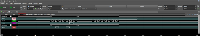
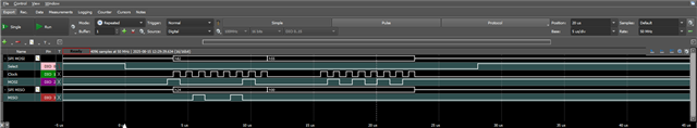
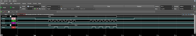
The diagrams clearly show (Fig 7-5, Fig 7-6) a SDI change on the rising (low-to-high) edge (blue and red lines added for clarity) of SCK.
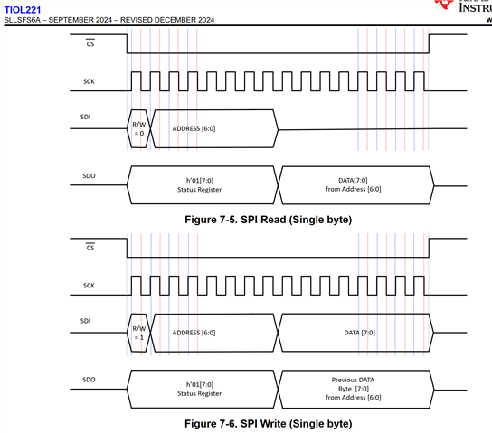
The text of the data sheet states (bold highlight added)
"The SPI controller must generate clock and data signals in SPI MODE0 (clock polarity CPOL = 0 and clock
phase CPHA = 0) to communicate with TIOL221. The SPI input data on SDI is sampled on the low to high edge
of SCK. The SPI output data on SDO is changed on the high to low edge of SCK."
It seems this contradicts what is shown in the figures.
For a description of SPI modes see e2e.ti.com/.../faq-ads129x-what-are-the-correct-polarity-and-phase-cpol-cpha-spi-settings
Could you please clarify which is correct for the TIOL221?
Thanks for your assistance.
Kind regards