Tool/software:
Hi team,
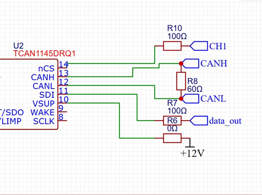
1. When using the TCAN1145DRQ1, I noticed a 200mV difference between the dominant common-mode voltage and the recessive common-mode voltage. Is this normal? What are the main reasons for this discrepancy between the dominant and recessive common-mode voltages? Is a difference of less than 500mV considered normal?
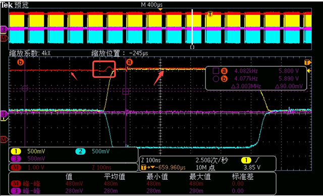
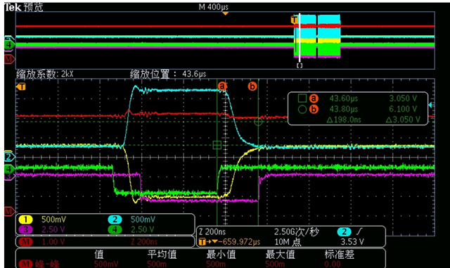
2. Is the TCAN1145's TX and RX delay time related to RL (termination resistor)? Does this delay time correlate with the length of the canL and canH traces? I've measured different delay times with different RL resistances, with a 30-40ns difference between 120Ω and 60Ω. Because the CANH and CANL traces are quite long (about 26cm), I suspect the delay time is related to the traces. Is there a specific linear relationship between the canH and canL trace lengths and the delay time?
RL = 60Ω, ch3 is tx, ch4 is RX, ch1 is canl, ch2 is canh
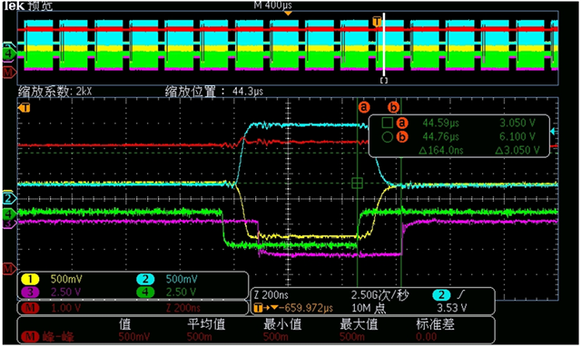
RL = 60Ω, ch3 is tx, ch4 is RX, ch1 is canl, ch2 is canh
BR,
Ethan