DS100MB203: 10GBase-R PHY Interface Packet Errors

Part Number: DS100MB203
Other Parts Discussed in Thread: DS280DF810, DS250DF230, DS560DF810

Tool/software:

Gooday, 

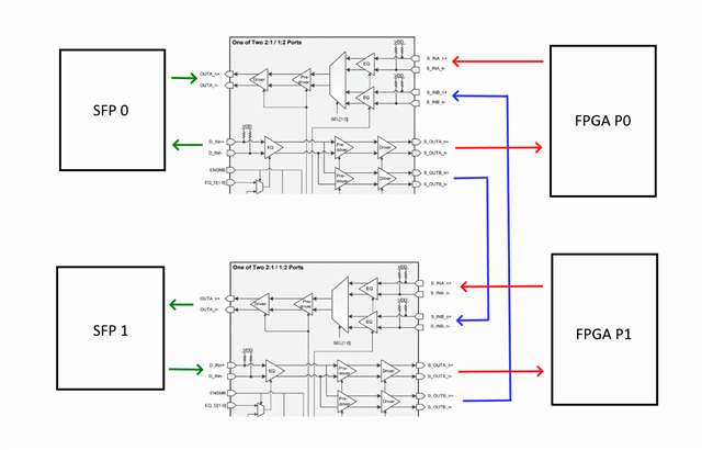
I have a design that uses the DS100MB203 between a FPGA host and 2 10GBASE-T1 PHYs where the SERDES is configured as 10GBASE-R.

/cfs-file/__key/communityserver-discussions-components-files/138/1108.UMAR_2D00_10G02.pdf

There is a passive MUX between the DS100MB203 and the PHYs/SFP ports, which are used to select which end point to use.

In PHY mode (PHYTX/RX) the interface works at full speed from the FPGA to the PHY, however packets are lost and have errors when traveling from the PHY to the FPGA through the DS100MB203.

Above is a picture of the transmitter eye mask of the PHY.

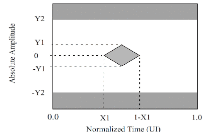
Y1 and Y2 are minimum 170mV and maximum 425mV respectively. 

Can you suggest what settings the MUX should have or is there anything in the design I may have missed?

Notes:
I have tinkered with the I2C registers in the MUX for CH4 (D_IN0 – S_OUTA0) which is one of these receive paths. Changing the EQ or DEM registers above 0 seems to stop the traffic all together and the VOD and RXDET registers seem to have no affect. 

Also, when I place my finger on the SERDES traces, this seems to reduce the number of errors, and in some cases remove them all together. Maybe this points to something.

Any help would be much appreciated. 

Thank you

  • Hi Luke,

    Apologies for the delay on your other thread.  For some reason there appears to be an E2E bug where I'm having difficulty responding.

    Regarding your other thread, typically EQ/DEM are optimized using some method to evaluate the signal quality.  This take the form of a scope, on chip eye monitor, or BER measurement.  If the insertion loss for a channel is known, this can help inform an initial EQ value.  Beyond this, it is often a matter of increasing and decreasing values and seeing how this impacts the link quality.

    A few thoughts:

    • Do PHY0TX/PHY1TX have AC coupling?
    • I'm wondering if DS100MB203 could be over-equalizing the signal.  Touching the SERDES traces would typically add capacitance.  This would lower the characteristic impedance and might increase insertion loss.
      • What is the insertion loss between PHY to DS100MB203 and DS100MB203 to FPGA?
      • Is it possible that the PHY is applying some pre or post cursor emphasis?  Combined with CTLE from DS100MB203, this might over-equalize the signal.

    One additional note:

    • If the FPGA/PHY have some sort of receiver adaptation, when you change DS100MB203 settings, you may also need to trigger a re-adaptation to the signal.

    Thanks,

    Drew

  • Hi Drew 

    Thank you for the help.

    So it seems you were right on the money when you said "Is it possible that the PHY is applying some pre or post cursor emphasis?"

    I had the same assumption that my finger was adding some insertion loss and we were only recently able to tune the Serdes transmit signal after gaining access to some non standard PHY registers.

    It seems that the default "post-cursor ratio" was set to 10/45. I imagine this is some sort of gain. 

    After changing that to 4/45, the errors dropped to 0. 

    Just 2 more questions :

    Can I assume that this problem could never really be fixed with any settings in the DS100MB203, since there isn't any de-emphasis options on the inputs of the MUX?

    And lastly, regarding the EQ/DEM tuning for direct attach cables, is it typical in the networking industry that with direct attach cables the EQ needs to be tuned depending on the cable and length? Or should all SFP ports on 10G equipment work as standard with no packet loss on all direct attach cables and length? I am trying to figure out if this is even a problem for our hardware.

    Thank you again

  • Hi Luke,

    Glad to hear that you were able to identify the issue!

    It seems that the default "post-cursor ratio" was set to 10/45. I imagine this is some sort of gain.

    Yes, this sounds like some post-cursor boost.

    Can I assume that this problem could never really be fixed with any settings in the DS100MB203, since there isn't any de-emphasis options on the inputs of the MUX?

    Not sure if I'm misunderstanding you, but I don't think de-emphasis is the ideal solution here.  De-emphasis and post-cursor are actually very similar and are typically seen as a configuration option on the TX of a high speed device.  They both have a goal of pre-distorting the signal by increasing the high-frequency content in order to compensate for the insertion loss of the channel following the TX.  Applying more de-emphasis to the signal the DS100MB203 is receiving would actually degrade performance.

    In this case, depending on how much post-cursor was being applied, it's possible that the signal was already over-equalized at the receiver of the DS100MB203.  Even if the DS100MB203 is configured as a limiting redriver (increasing eye height), it will propagate any jitter that is not improved by the CTLE.  The DS100MB203 CTLE also applies a minimum boost of about 5 dB, which can make jitter worse if there is not some pre-channel insertion loss.  For low insertion loss pre-channel, you may observe best performance without any TX post-cursor.

    And lastly, regarding the EQ/DEM tuning for direct attach cables, is it typical in the networking industry that with direct attach cables the EQ needs to be tuned depending on the cable and length? Or should all SFP ports on 10G equipment work as standard with no packet loss on all direct attach cables and length? I am trying to figure out if this is even a problem for our hardware.

    Often some sort of adaptive equalization is used to help mitigate variation when switching between DAC and optical modules.  With that said, it's still pretty common that between DAC and different types of optical modules, different settings may need to be used to get optimal performance.

    My understanding is that from a networking customer perspective, a typical user would not need to tune EQ.  However, from an engineering perspective, depending on the range of insertion loss and host capabilities, some tuning might be required.

    Thanks,

    Drew

  • Hi Drew

    Thank you very much for all of the responses.

    I just want to elaborate on our design a little more with a few questions.

    Above is a simplified TAP channel of our device. We use the DS100MB203 in such a way that it allows us to connect the SFP ports directly to the FPGA end points (using the SEL pins) for an end point mode and also allows us to connect the SFP ports back to back in a TAP mode. I have the fanout mode always enabled which allows us to receive the traffic when the SFP ports are configured in back to back mode. 

    I have basically been trying to figure out settings for the DS100MB203 so that the traffic is passed with no errors in all test cases (i.e. direct attach cables (DAC), RJ45 SFP modules, etc to the SFP ports).

    1. I have test case where I connect SFP0 to a Marvell switch (MAC) configured with 10GBASE-R using a DAC and I have a 10GBASE-R RJ45 SFP module in SFP1. When I have the DS100MB203 in SATA/SAS, PCIe GEN 1/2 and 10GE mode (MODE pin = 0), the traffic that goes has a huge amount of errors and drops. However when I change the mode to AUTO (PCIe GEN 1/2 or GEN 3), MODE pin = FLOAT), the traffic largely works. However from what I understand SFP modules in 10GBASE-R mode does not typically have link training. What is happening in the DS100MB203 that might help this? Can you maybe elaborate a little on "transparently allows the host controller and the end point to optimize the full link and negotiate transmit equalizer coefficients" from the datasheet? Does the DS100MB203 itself do some sort of auto equalization in this mode?

    2. When in AUTO mode, do the EQ and DEM pin strappings get ignored?

    3. In general I have found that the traffic has better results when in end point mode (red lines) and the FPGA loops back the traffic between the 2 FPGA ports. Is this design fundamentally flawed in some way (that I do not see) by connecting the DS100MB203 back to itself (blue lines)? i.e. there are no EQ or DEM settings that will work 100% for the loopback mode (blue lines) because typically end points are connected to those. The blue line traces are basically just ac coupled traces that are about 10mm long. 

    Thank you for the help

  • Hi Luke,

    1. Please see the E2E thread below.  Although this is a different part, the function of the mode pin is the same.  In KR mode, the device acts as a linear signal chain, while in PCIe gen1/2 mode, the device acts as a limiting signal chain.  The "AUTO" mode is designed for the device to automatically select linear or limiting depending on data rate.  PCIe gen1/2 do not have link training, while gen3 implements link training.
    DS100KR800: he difference between the 10G mode and 10G-KR mode

    It's not clear to me why this behavior would be specific to the RJ45 SFP modules.  Have you tested with optical modules?

    2. No, AUTO just automatically selects linear/limiting mode.  It seems like you're observing better performance in linear mode.  If you switch to KR mode, you should see similar behavior to AUTO.

    3. I think a potential challenge you may be running into is that EQ and DEM only compensate for jitter due to ISI.  Other forms of jitter, like Rj, cannot be compensated for by the DS100MB203.  Because of this, designs implementing cascading redriver devices will be more sensitive to signal integrity challenges.

    Thanks,

    Drew

  • Hi Drew

    1. I see, thanks for clarifying this. This issue is specific to the Marvell switch that I am testing against in direct attach mode. However, when I connect 2 x SFP 10GBASE-T modules to the SFP slots in my diagram, the traffic looks fine when in limiting mode, but I start to see errors in the linear mode. I only change the MODE, all other strapping is the same. Specifically have EQS/D set to 00 and DEMS/D set to 0R. Does this make some sort of sense?

    2. Yes you are right, I see similar behavior with AUTO and KR, so I imagine they are both being set to linear mode. 

    3. This might be the limiting factor in our design, where there is no one pin strapping setting that will work for all combinations of devices connected to the SFP ports. Especially 2 cascaded buffers. 

    4. Is there any chance you could suggest any other devices from TI that could accomplish something similar for our design in the block diagram? Anything I could look into?

  • Hi Luke,

    1. Not sure if I am misunderstanding something.  I believe in the previous post you said that you saw errors in SATA/SAS, PCIe GEN 1/2 and 10GE mode (limiting mode), but in the most recent post you said you're seeing errors in linear mode.  Can you help clarify?

    4. Is pin control of the MUXing functionality a requirement for your design?  We have devices like DS280DF810 that have automatic adaptation, but would require I2C configuration to switch the crosspoint.

    Thanks,

    Drew

  • Hi Drew

    1. So to simplify to just 2 test cases. One test case (lets call it A) is where I put 2x 10GBASE-T copper SFP modules into the 2 SFP slots (in the block diagram). Test case B is where I connect the Marvell switch I mentioned using a direct attach cable to one of the SFP slots and another direct attach cable into the other SFP slot going to a 10G FPGA based packet generator we have developed. And to confirm, our packet generator works when directly attached to the marvel switch (no DS100MB203 in the picture). 

    For test case A, I see no packet drops when in GE mode (limiting, MODE =0). But when I change this to linear mode (SATA/SAS, PCIe GEN 1/2 or 10GBASE-KR) I consistently see errors on some or all of the ports. Then conversely in test case B I see a huge amount of errors and packet drops in limiting mode, but this dramatically improves when in linear mode (still not 100% but at least all of the packet drops stop and the one direction of traffic starts to work). 

    2. We could change to I2C controlled and the DS280DF810 might work, but I would have to cascade this chip again for our design. Would cascading be guaranteed to work do you think? 

    Thank you

  • Hi Luke,

    1. It would be interesting to look at the output of DS100MB203 and one of the 10GBASE-T modules on a scope, but I understand that may not be possible.  I am wondering if output of 10GBASE-T module is lower amplitude, or has some characteristic where limiting mode is beneficial.

    For DAC case, I'm wondering if errors are related to the interaction between adaptation on the Marvell switch and limiting vs linear mode.  Do you have the ability to check any sort of adaptation details on the switch?

    2. DS280DF810 is a retimer.  This enables it to "reset" jitter within a signal, which enables cascading retimer devices.  We would expect cascading these devices to work.

    A few options come to mind:

    • DS280DF810: Has high channel count; Also has high minimum CTLE boost.  Will need to ensure minimum insertion loss in layout in order to avoid over equalization.
    • DS250DF230: Has improved CTLE with low minimum boost setting, but has lower channel count.
    • DS560DF810: Has high channel count and low minimum boost setting.  Also has option for GPIO MUX crosspoint switching.  Configuration of this device is quite a bit more complicated than DS280DF810/DS250DF230.  TI has an API written in C to facilitate I2C configuration of this device.

    Thanks,

    Drew