This thread has been locked.

If you have a related question, please click the "Ask a related question" button in the top right corner. The newly created question will be automatically linked to this question.

SN65HVD71: Series Resistor,Termination Resistor and Pull up and pull Down for Fail Safe.

Part Number: SN65HVD71


Tool/software:

Hi,
I have few questions design related

My Application would be using around 40mA meaning 40mA RS-485 IC would have to pass through it with around 1.8m Cable between Two devices 
Communication mode will be UART between just  devices a Master and Slave.

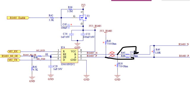
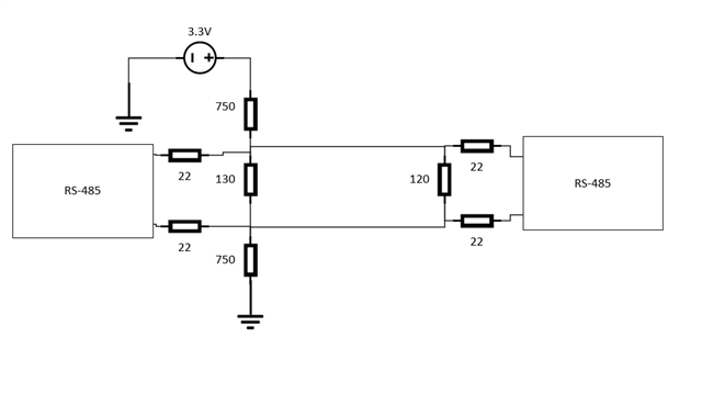
1.Do i need Pull up and pull down for extra protection saying IC have Failsafe operation and how should i decide the value of pull up and pull down.

2.As RS-485 Connector would be exposed to outside world there is always risk of ESD so my standard says 8kV air and 4kv contact so i need to design in such a way that it can sustain ESD,so should i go with just TVS diodes or zener with a series Resistor?.

3.Is there a Need of series resistor and what should be its value? and postions of series resistor before protection or after.

4.Need of Termination resistor as i have just one device connected to my master is there still  a need for termination resistor? and what value should i choose and how will it influence my current consumption saying my product is battery powererd.

  • Hi Harsh,

    1. You don't need pull-ups/pull-downs on the differential bus as this device has integrated idle bus, open bus, short circuited bus fail-safe protection. I.e. when the bus is open circuited, idling, or short circuited the output on the "R" pin will be a logic high. For the "R" pin output however it is generally a smart idea to add a pull-up as those generally are required in most UART applications - this value will vary but generally between 1.5k and 10k are the most common values (usually 1.5k to 4.7k are the most common - but there have been 10k based applications that work fine). 

    2. TVS diodes are always going to be the general recommended protection - usually some SM712 type devices are most common for RS-485 applications. 

    3. You don't need the series resistor - but it can increase robustness of the node if you add a pulse proof 10 ohm resistor (so it will be thick film or wire wound) between the IC and the TVS diodes - this resistor is not necessary in most applications but it would be go IC -> Series Resistance -> differential termination (120 ohms between differential pair) -> TVS diode (TVS diode should be close to connector) -> connector to rest of RS-485 bus. 

    4. So in general the RS-485 standard says you need to have 2 120 ohm terminations at the start and end of your bus - so for point to point applications like this one  means that each differential pair is terminated with a 120 ohm resistor and that the transmission media has a characteristic impedance of 120 ohms that is the standard and it is always best practice to follow. This device is full duplex so that would be 4 terminations - 2 on each node, one between A and B and one between Y and Z. 

    That being said  not all applications really need a termination - it is primarily going to depend on data rate and the specific device you are using transition time (fastest listed value). 

    Before we even look at specific data rate (this device has a max of 400kbps - if you need faster you need to pick a different device). 

    For the SN65HVD71 the minimum differential driver time is 100ns - that means the longest unterminated piece of tranmission line allowed before you start seeing reflections is based on the following equation:

    L <= (t_r,t_f (min))/10 * Vp - where tr,tf(min) for this device is 100ns, and Vp is the phase velocity of the signal through the transmission medium (so it will be some percentage of C - standard RS-485 cable has a Vp of 78% * c - but Vp is a physical property of the PCB traces and cable between the two nodes). To keep things simple from an example point of view let us just assume Vp = 0.78*c for your system (it might not be that so you should double check on your side) 

    L <= 100ns/10 * 0.78 * c -> 2.338m ; i.e. if your Vp is 0.78c the max unterminated stub length for this device is 2.338m - anything less than that doesn't need termination and you can pretend there are no transmission line effects. If you go above 2.338m the reflections produced will only be at signal transitions as this condition only concerns itself with the signal transition but this is the most strict length requirement in the system - you won't be seeing reflections due to the direct data rate with only 1.8m and a max data rate of 400kbps. 

    Most likely in your application you don't need termination - however I would add a resistor pad for the terminations in case you find you do need them later (which is pretty unlikely - this is a very slow device so you get a little more room before you need a termination).

    Best,

    Parker Dodson

  • Hi Parker,
    Nicely Explained
    I need few more responses

    1.What package should i go with for 120 ohm considering i am have pull up and pull down which are pulled up by 4.7K and 3.3V as they would form a voltage divider.

    2.For series i am planning on going with 10 ohm resistor with 18V zener as IC is already ESD protected upto 12kV which more than what my standard requirement 
    So what package should i go with for 10 ohm resistor.,

  • Hi Harsh,

    1. It is less about package size and more about power rating - generally we'd typically suggest at least a1/8W resistor at 3.3V due to the current the driver dumps over the terminations - the common mode biasing you have set up will put a very small amount of current through the terminations (at 3.3V if you have 1 pair of pull-up/pull-down resistors you would be putting ~20mV across the terminations and with 2 pairs of pull-up/pull-down (one at each side of bus) you would only be putting about ~40mV across the terminations which is only around 13uW max). A safe estimation for resistor power rating is VCC^2/R_term - i.e. if one line of the bus was shorted to VCC and the other ground you could force VCC across terminations - which at 120 ohms with 3.3V gives you 90.75mW - so 1/8W resistor gives you a good amount of margin - you could probably get away with a 1/10W resistor but you would get less margin. If you go with a 1/8W rating you can get resistors as small as 0805 package but if you are okay with less margin with 1/10W you can go with 0603 or even 0402. For reference typically the driver is only generating a 2V output differential so that would be 33.3mW - so you could probably get away with the 1/10W in most cases.

    2. The resistor we suggest for the series resistor is CRCW060310R0JNEAC - it is a 0603 package. A note on the zener diode is that the A/B/Y/Z pins are only rated to 16.5V absolute max voltage - so transients longer than ESD pulses above 16.5 but below zener conduction point could damage device - the series resistors will help here - but it does add risk. The reason why SM712 TVS diodes (the one we typically suggest is CDSOT23-SM712) are used for these types of applications is because they are made with RS-485 devices in mind - while they technically can clamp above the abs max ratings - that requires a lot of current to do so (more than a typical transient would provide) and they start conducting outside of RS-485 standard bus voltage operational range - so they are generally great for most RS-485 applications - and  they are usually very cost effective. 

    Best,

    Parker Dodson

  • Hi,
    Thankyou for your response
    What am planning is 
    1.DNP for Failsafe as i trust the IC

    2.DNP 120 ohm 0603 package as my length is less than 2 meter can you give me calculation by which i can prove it.

    3.I am Adding TVS diode of 7V and 19V Clamping voltage at 8kV and the pin max can handle is 16.5V according to datasheet and 24mA so am expecting around 18V to appear on my TVS diode and 16V max my IC can handle divide by 24mA that much value ofcourse i cant use but max 22 ohm i will choose of 0603 package.

    4.Now if i see 8kV directly i will choose one more clamping diode which will take care of the current such as no current will flow thorugh my pin

  • Hi Harsh,

    Okay thanks for the information. 

    For the calculation to show if you need a termination or not - the most strict is as follows:

    L <= t_r,t_f(min)/10 * Vp

    t_r,t_f(min) - is the minimum differential transition time (fall or rise time - whichever is quickest if they are listed as different specs) listed in datasheet - which is 100ns for this device.

    Vp - this is the phase velocity of the transmission media - which is going to be c * x where x is a value between 0 and 1 and c is the speed of light. You will need to check the Vp of your PCB traces and cable between nodes as this is a system parameter. Most RS-485 cable is going to have a Vp of appx. 0.78*c - but double check as this will change the max length. 

    with Vp = 0.78c and t_r,t_f(min) = 100ns that would give you a max unterminated length of appx. 2.34m - lengths longer than that could reflect at signal transitions (where the most high energy is at during the signal). This is a small portion of the total signal. 

    See Below for more detailed considerations that include all energy in data stream - not just high frequency - this isn't as critical to your specific application but you may find this information helpful. 

    -------------------------------------------------------------------------------------------------------------------------------

    The other considerations would be data rate derived - but would result in longer busses. I.e. the other analysis you could do is looking at harmonics and fundamental frequency. For example let's say you were using this device at max speed of 400kbps - worst case frequency on this is going to be a 200KHz square wave - that means fundamental frequency is 200KHz - since worst case is a pulse train at 200KHz that means we can ignore even harmonics and only focus on odd. 

    Reflections can occur and be harmful to application when the signal wavelength is greater or equal to 1/10th of the electrical length of the system - which in this case is the total bus length. 

    If we look at fundamental frequency and convert that into wavelength --> Vp/f = wavelength if we assume Vp = 0.78c then the equation is 0.78c/200KHz =1.17km and 1/10th of that is 117m - so you wouldn't expect reflections from the fundamental frequency until you hit a bus length of 117m. 

    However we also need to consider harmonics - typically we would cut off around 9th harmonic - so we can just look at that. 

    Nth harmonic wavelength = Vp/(n*f) which will give us about 13m of unterminated cable before reflections would occur due to the 9th harmonic. 

    So the most strict measure is based on the transition time of the drivers - which is what gets you the 2.34m number while you need at least 13m of unterminated cable before harmonics will start having an effect. However the largest energy component is the fundamental and you wouldn't have that reflect until 117m about. 

    So essentially there are three checks:

    Reflections could begin to show due to driver transition time: 2.34m

    Reflections due to harmonics could begin to show (9th): 13m

    Reflections due to fundamental could begin to show: 117m 

    How you should read this is there is no risk of reflection issues on bus for bus lengths less than 2.34m - there is a small risk of reflections between 2.34m and 13m and much higher risks as you go longer. So something like 2.5m may have reflections without proper termination matching - but it would be very small most likely. 

    Remember - I am using Vp = 0.78c - but that may not be true for your system - it is just a very common Vp value for RS-485 systems so always double check as the lengths may be slightly different due to differences in phase velocity of signal. 

    ----------------------------------------------------------------------------------

    2. The 22 ohm resistor should help mitigate a lot of risk - but if the device pins are directly exposed to above max ratings for a sustained period of time you could see part damage - so I would ensure that the resistor + TVS combo works for your system during system qualification. 

    Please let me know if you have any other questions!

    Best,

    Parker Dodson

  • Hi Parker,
    Thanks for your detailed response
    I have few questions

    1.This is my final circuit which i would be using 
    2.Do you see any challenge in any part of it?

    3.Trusting Failsafe Biasing Feature i have DNP R43 and R50 and 120 ohm as from my calculations my cable length is 2m and baud rate is 9600
    4.How did i calculate 750 ohm is i have issue of area on my pcb i need to choose 0402 package
    0.2=Vcc*Rt/Rt+2R where Vcc is 3.3 Rt is 120 ohm and 0.2 is difference i neeed between A and B
    So by that i get around 820 ohm 
    Then i calculate I using 3.3/120+2(820) =1.87mA
    By this i can get difference between Va and Vb =1.824 -1.476 which is greater than 0.3V 
    5.My question to you is did i do i properly or did i miss any part of calcualtion 
    6.Even if i ignore 120 ohm my package of pull up and pull down would go high am i right?

    7.Decoupling my datasheet says 100nf i have added 1uF am i right doing it?

    8.I am enabling and disenabling my VCC line by a mosfet which would have minimum drop so that it doesnt affect my Vcc

  • Hi Harsh,

    Series Resistance Placement

    So in general - one note that I have right away is the placement of the fail-safe resistor pads w.r.t. series resistors.

    Essentially it should be:

    IC --> Series Resistors --> Fail-safe Resistor pads & Termination Resistor pad. 

    Fail Safe Resistor Calculations

    As for the calculation of the fail-safe resistors:

    (All these calculations are found here: https://www.ti.com/lit/an/slyt324/slyt324.pdf?ts=1757001275138&ref_url=https%253A%252F%252Fwww.google.com%252F

    VAB = VS/((0.036 * RFS) - 1)

    Where RFS is your fail-safe resistor values (R43 and R50)

    Generally you would would pick VAB = 250mV (200mV for RS-485 compliant devices + 50mV margin) 

    VS = 3.3V (the pull-up voltage)

    You have set RFS to 750 - this equation assumes that only one node has fail-safe resistors (only one node should have fail-safe resistors - the single pair will apply bias to the entire bus. 

    VAB = 3.3/((0.036 * 750)-1) = 126.9mV

    So the current set up does add margin to the devices fail-safe (the device has integrated fail-safe so VID >= 0V is read as high - so a idle bias of 126.9mV will add margin to that - but this value isn't sufficient for classical RS-485 as idle VAB should be >= 200mV for classical RS-485). 

    With a 3.3V supply you won't really be able to get 250mV bias voltage - but for this device that shouldn't be an issue as you don't even need the fail-safes (keeping the pads for them is still a good idea). 

    So 750 ohms is fine for this device. 

    You could try to lower it to get more bias - but that is unnecessary for this device. 

    However if you want to max this out there is a check you can perform. 

    You need to find RINEQ which is just equal to 1/(1/RCM - 1/RFS) where RCM = 375 ohms (from RS-485 standard) and RFS is the fail-safe resistor value. 

    Next you would need to calculate how many unit loads the fail-safe network uses

    n = UL/RINEQ = 12k/RINEQ

    UL = one unit load = 12k

    Using your current setup:

    n = 12k/750 = 16 - so your current setup can handle up to 16 UL nodes - the current device you are using is 1/8th unit load so with 750 ohm resistors you could support 16*8 nodes - since you are only using 2 you should be good there. 

    Other Schematic Concerns:

    1. You only need 100nF on the VCC pin - you don't need 1uF  - but I don't think it should cause too many issues to keep it - but it is not required. 

    2. You can have the FET shutting on and off the device - but you need to ensure that the input voltage >= 3V and ensure VCC voltage isn't < 3V.

    3. If you are using UART typically the "R" pin is pulled up to VCC usually through a 1.5k resistor. It isn't a device issue - it is that many UART applications will have false start conditions if the "R" line isn't pulled high for idle conditions and the "R" pin is hi-z. 

    4. If you have the fail-safe resistors installed - they should only be installed on one node. 

    5. If you have the fail-safe resistors installed - the node with them installed the termination resistor cannot be 120 as the load impedance has changed for the load - you would need to use 130 ohms - please see below:

    Best,

    Parker Dodson