DP83825I: Ethernet Communication problem (phy used with STM32H757XI)

Part Number: DP83825I

Tool/software:

Dear TI Team,

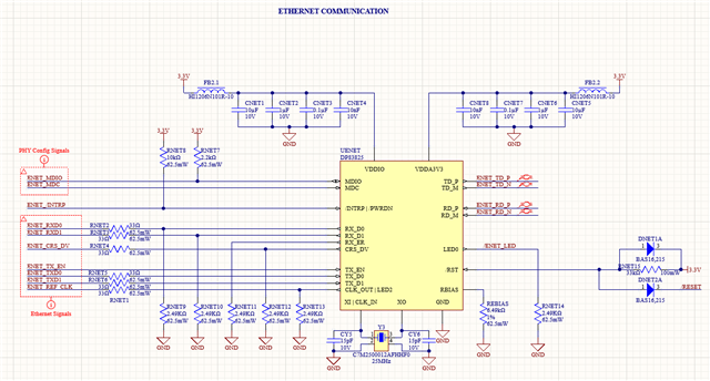
We are using a STM32H757 microcontroller with the DP83825I phy (linked together through the RMII interface) where the phy is linked to a 25MHz quartz to be able to give a 50MHz reference clock to the CPU. Some communication losses happened when an ethernet cable is plugged into the RJ45 connector (RJ45 with integrated magnetics). We checked the MDIO + MDC signals and RX0-1/TX0-1 signals with the reference clock given by the phy and everything seems to be ok (compared with an other circuit with the phy linked to a LPC54606 microcontroller from NXP which works correctly).

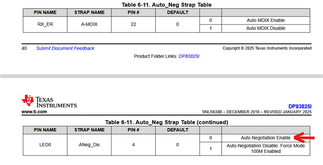
However, when we checked the registers configurations, we noticed that some registers (LEDCR, MLEDCR and PHYSTS for example) which are not configured by our program did not have the default values inidcated by the datasheet. As consequences, the activitty LED (linked on the LED0 physical pin of the phy), has an inverted polarity "by default" (bit 7 of the LEDCR register is 1 by default instead of 0).

Please find in attachement, the schematics about the phy wiring :


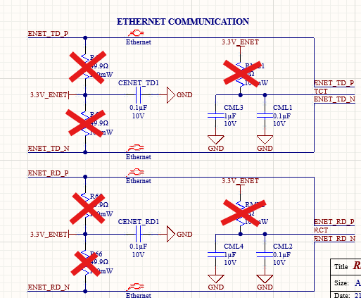
(the crossed out components are not populated)

Thank you very much,

Best regards,

Benjamin

  • Hi Benjamin, 

    LED0 auto-sets polarity based on the strapping. If the LED0 is pulled down at the power ramp, the LED0 will be active high and vice versa. It looks like the LED0 is pulled down in your schematic. This will cause the LED0 polarity to be active high instead of active low. 

    Best,
    J

  • Hi J,

    Thank you for your answer.

    Indeed, it seems it solved the LED problem (not the ethernet communication problem) but, in the datasheet, it is written in the Straps Configuration section that this pin is used to enable or not the auto negociation capability and not for the LED polarity, that is the reason why I soldered a pull-down resistor (now, the auto negociation capability will be enable by our program through the register writing).

    Best regards,

    Benjamin

  • Hi Benjamin, 

    You are correct. However, the strapping also affects the LED0's polarity. 
    Could you specify what sort of communication losses are there? What is the test and the setup? How often does it happen? Does this happen with specific link partner or all link partners?

    Best,
    J

  • Hi J,

    To start with the communication tests, I sent pings to the IP address of the device through the command prompt of Windows on my computer. The device with the phy soldered sometimes answered, sometimes not and sometimes, after several fails, I have feedback in the command prompt window saying that it cannot reach the element at the IP address.

    The device with the phy and my computer are linked to a MikroTik or a Cisco switch (for example a hAP mini and a hapac2 from Mikrotik). It happens with all link partners.

    Best regards,

    Benjamin

  • Hi Benjamin, 

    Thank you for your input. Have you checked if the PHY is alive when the ping fails? 
    Can you verify that the power to the PHY is there, and that the clock is being fed into the PHY? Can you access the registers when the PHY is not responding to the ping?

    In addition, have you tried directly linking the PC and the PHY to see if you can consistently get a response? 

    Please let me know. 

    Best,
    J

  • Hi J,

    We already checked all of these aspects of the communication with the PHY (checked the supplying voltage drops, the Quartz signals forms, the RMII reference clock signal from the PHY to the CPU, the RMII RX0-1 / TX0-1 signals, the MDC and MDIO signals).

    We may have a new line of inquiry that we are currently checking, I will give you feedback if it fixes our problem.

    Best regards,

    Benjamin

  • Hi Benjamin, 

    Another way to see if there are any issues of the data path would be to use the loopback mode.
    You can use reverse loopback mode on DP83825 to see if there are any packet losses from the link partner to the DP83825.
    In addition, you can use MII loopback to verify if there are any data loss on the MII path. 

    Reverse loopback can be enabled by setting bit[4] in the BISCR (16h).
    MII loopback can be enabled by setting bit[14] in the BMCR (0h) and bit[2] in BISCR (16h).

    If there are no problems detected after doing MII loopback and reverse loopback on DP83825, I would suggest directly linking the PHY to the PC and ping as it seems it could be a network routing issue.

    Best,
    J