Part Number: ESD204
Other Parts Discussed in Thread: STRIKE
Tool/software:
Hi
Please provide an ESD204 measurement report (the requirement is that the low-voltage surge device tested in TI's lab be verified, as the surge test conducted by the third-party lab is IEC 61000-4-5, and the kV level is not discussed).
After clamping, components behind the ESD204 still fail. The issue can be reproduced using the low-voltage surge test.
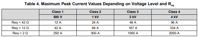
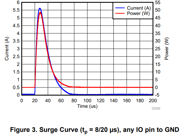
Please provide an 8/20µs low-voltage surge test, starting at 3V and increasing to 20V (in 1V steps, assuming the device has a 2ohm internal impedance for current limiting). This indicates that leakage current exceeding 5A may occur above 11V.
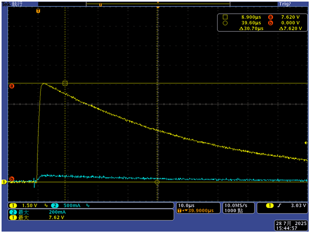
As shown in the figure, I have three key observations for this test. Please refer to the graph below, which shows an 8/20µs surge signal. Observe the voltage and current changes of the TVS. The blue waveform represents the current, and the yellow waveform represents the voltage change.
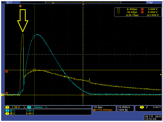
1. When the TVS operates, I would like to understand the spike voltage changes generated by different low-voltage surge signals (as indicated by the arrows) when the TVS activates. (This phenomenon is not apparent from the clamping voltage presented in the datasheet.)
2. When the TVS is actuated, the voltage behavior (spike peak voltage, clamping voltage) is measured when the leakage current is less than and close to the Ipp current.
3. When the TVS is actuated, the voltage behavior (spike peak voltage, clamping voltage) is measured when the leakage current is greater than and close to the Ipp current.
If the leakage current generated by an 8/20µs surge signal exceeds the Ipp withstand of the ESD204 TVS and causes burnout, please provide measurement records.
If there is a higher VBR TVS product (assuming 25V), will the Spark of the yellow arrow also be pulled high?
If the TVS is not activated, can I directly observe the 8/20uS Surge signal?