DS280BR810: DS280BR810

Part Number: DS280BR810
Other Parts Discussed in Thread: DS280BR820

Tool/software:

I hope this email finds you well.

I am reading the following Guide.

DS280BR810, DS280BR820
Programmer's Guide
SNLU188B–October 2015–Revised September 2016

Could you please provide information regarding the characteristics of Table 25 under what conditions?

Conditions:
・What level will be input into the DS280?
・What are the characteristics of the transmission line preceding the DS280?
 (For example, the Insertion Loss at the Nyquist frequency)


Best regards,

  • Hi Akimaru-san,

    • These were measured using a VNA with an input signal power that enabled the output of DS280BR810 to stay within the linear region of the device.  For high CTLE values, the input signal amplitude would be small.  For example, if output signal looses linearity >1Vppd and you are testing a CTLE setting with 20dB of boost, input signal must be <100mVppd.
    • The transmission line before and after the device is either calibrated out during VNA cal, or de-embedded in order to avoid impacting the boost measurement.

    Thanks,

    Drew

  • Dear E2E team,

    Thank you for your response. Furthermore, I would like to inquire for more details.

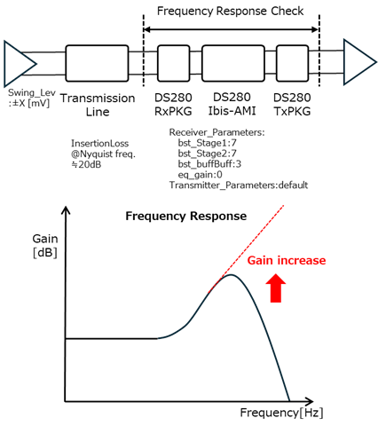
    I am checking the frequency response between the input and output in the DS280's Ibis-AMI (including the package). As I increase the output amplitude of the Tx Driver (Swing_Lev=±X[mV] in the figure), the gain in the high-frequency range of the frequency response between the input and output increases.

    When the output amplitude of the Tx Driver is ±50mV, a typical frequency response of a 2pole-1zero CTLE is observed. However, as I increase the amplitude to ±100mV, ±200mV, and so on, the gain in the high-frequency range continues to increase. What kind of functionality leads to this characteristic?


    Best Regards

  • Hi Akimaru-san,

    The DS280BR8x0 can operate as a linear or limiting redriver depending on how its configured.  In the IBIS-AMI model, this is controlled by the `sel_fir` variable.  Which mode is the sel_fir variable in?  If you change it, does this impact your observations?

    Thanks,

    Drew

  • Hi Drew,

    Thank you for your confirmation.
    I am using "sel_fir" at "0" (default linear mode).

    I switched to "sel_fir=1" and checked it. The output amplitude of the DS280 changed,
    but there was no change in the behavior I mentioned in my previous communication. 

    When the output amplitude of the Tx Driver is ±50mV, a typical frequency response of a 2pole-1zero CTLE is observed.
    However, as I increase the amplitude to ±100mV, ±200mV, and so on, the gain in the high-frequency range continues to increase.

    Best regards.

  • Hi Akimaru-san,

    Thanks for confirming which transmitter mode you're using.

    Is it possible for you to share your ADS project?  I'd like to take a look at this behavior.

    Thanks,

    Drew