TPSM846C23EVM-806: i2c interface

Part Number: TPSM846C23EVM-806
Other Parts Discussed in Thread: TPSM846C23,

Tool/software:

Good day.

We will be using TPSM846C23 for our new evaluation board design. 

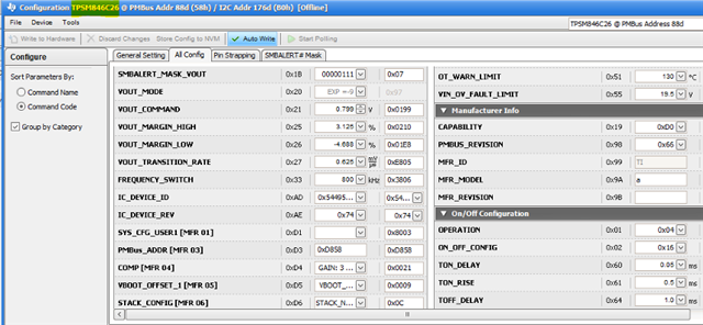
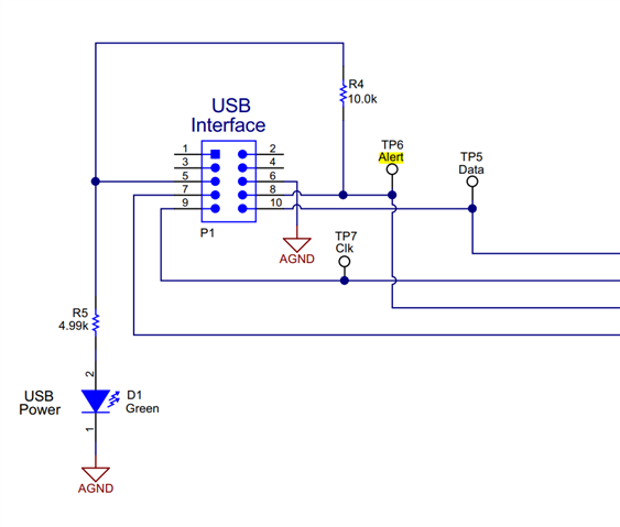
As part of validation, I've ordered TPSM846C23EVM-806 module to verify its i2c functionality but I couldn't get it working. I've been using Raspberry pi as a i2c interface and control the voltage but I couldn't get the communication working between the 2 devices.

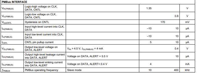
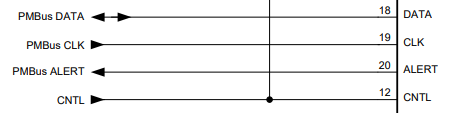
Q1: TPSM846C23EVM-806 says its a PMbus compatible.. I believe it should work with I2c as well as they have both the same protocols?

Q2: Would raspberry pi works as a master i2c to verify this module? if not.. any other devices/interface i can use to verify it? 

Or am i just missing any important technical details of the module to get it working?

Thanks,

Jay

  • Hi Jay,

    The TPSM846C23 is a PMBus device so you got to make sure to communicate using PMBus 1.3 protocol. The way this device is typically sampled is by ordering the EVM which you already have done but additionally you can order USB2GPIO2 to connect device to computer and download our GUI to have access to all the digital features.

    This is how USB2GPIO2 dongle get connected in out EVM:

    https://www.ti.com/lit/ug/slvub26d/slvub26d.pdf#page=7 

    That way you don't have to do any coding or worry about doing write it a specific way, as that setup up along with our GUI automatically will recognize the TPSM846C23 device and display all the commands, along with the read values. It has a lot of functionality like monitor tab to keep up with IOUT/VOUT/TEMP etc., STATUS tab to keep track of specific error/s, and all commands page:

    I have not tried it with raspberry pi but the above should work. 

    Regards,

    Eileen

  • Hi Eileen,

    Thanks for the response.

    I am aware of the the USB2GPIO2  and software GUI. However, we already have our board design finalized and we cant and don't plan to use the gui/usb2gpio.

    My current set up is connecting both SDA, SCL and Gnd of TPSM846C23  and Raspberry Pi (or any i2c interface). 

    Have you tried or is it going to work with other i2c interface module? I would like to verify it and control the voltage output without using your gui/usb2gpio.

    Thanks,

    Jay

  • Hi Jay,

    If you can replicate the setup of USB2GPIO and are doing what the GUI does thru raspberry pi I think it should work. PMBus is a communication protocol built upon I2C interface so technically it should support it with some changes.

    Make sure to have the PMBUS related pins connected to your Raspberry PI in order to function, that would be ALERT, DATA, CLK, CNTL (this last one you may not need if you have it setup externally). 

    We don't have a setup/steps on using your method as we only support the setup previously mentioned, however few things I can tell you to look out for is: make sure when you are doing reads/writes that it's following SMBus format, this tends to be different than I2C, also make sure to follow data rate speeds allowed by device/pmbus protocol, this device particularly goes up to 400 kHz.

    DS doesn't go into PMBus details on individual bits that need to be written outside the main data but you can look up protocol here: https://pmbus.org/  

  • Hi Eileen,

    Since we were not using the  USB2GPIO, do i need to power up the USB interface/header (P1) to get the SCL and SDA up?

  • Hi Jay,

    SDA should equate to DATA pin and SCL to CLK pin. Not familiarized with changes for direct capability but if you can follow as below it should work:

    Another thing I forgot to mention is I2C communication has certain addresses reserved for special functions (don't know which ones), so be careful when selecting the device address thru ADDR0 and ADDR1 resistors.

  • Hi Eileen,

    Yes, I am aware of these and the SDA SCL pin.. Its just whenever i measure SDA and SCL pins I don't see any voltages which it typically 3-5V. 

    does it need to be powered up somewhere? 

    I only applying 12V into the TB1 Vin to power up the module.

    Thanks,

    Jay

  • Hi Jay,

    Earlier I added image of the voltages for those pins. Typically we have pull up resistors to ensure voltage stays low/high, but that is with our setup. I believe SDA and SCL raspberry pi lines should have internal pull up resistors, in which case you probably don't need to add it. If you aren't sure you can try an add some externally. If lines don't have pull ups, they will float and you wont read voltage. 

  • Hi Eileen,

    Sorry I overlooked first image you shared. On the pin#7 of the USB interface which is the CNTRL pin you added a 3.3V supply which is also tied up with PGOOD. Is the 3.3V coming from external supply?

    If I look at the original schematics.. there is already a 3.3V  coming from the BP3 pin of the chip going to CNTRL and PGOOD.

    Thanks,

    Jay

  • Hi Jay,

    The image I had attached earlier was from the 2PH EVM schematic, they named 3V3 for BP3, it should be the same thing. No external source.

    Another thing, you mentioned SDA and SCL pins are typically 3-5V. Make sure it doesn't go above abs max as its close:

  • Hi Eileen,

    Thats point taken.

    Raspberry pi I2c is also 3.3V - 5V range so it should be fine. My existing problem is I couldn't get any output voltage from the SDA and SCL pin of the TPSM module :( .. while SDA of SCL pin of Raspberry Pi are verified with 3.3V output.

  • Jay,

    Got it! Where you able to get SDA and SCL working successfully with DATA and CLK? If not, you may need pull up resistors but I believe Raspberry pi should have some internally. 

  • No luck so far. Im still measuring no voltage from the TP of Data and CLK of the TPSM. Thats probably the reason why it couldnt communicate.

  • Hi Jay,

    I looked a bit deeper into this and our typical setup. There is some connection in the USB2PIO userguide for reference. Based on that, it looks like SDA/SCL = DATA/CLK lines have pull up resistors to enable those communication lines.

    Our GUI and USB2GPIO setup has multiple options of pull up resistors 668 Ω, 1.1 kΩ, 2.2 kΩ, or open drain but 2.2k (is typical for 400kHz "fast mode" speed) to a 3.3V source. I'm guessing your SDA/SCL lines are open drain and therefore pulling low. 

    You can check your raspberry pi UG to see if this is already included internally and if you just have to do something to enable it.

    Let me know if that ends up working. 

  • Raspberry pi has its built i internal pull up resistors already for I2C. I've also tried adding extra externally but still couldnt get it working.

    My concern is that the module TPSM i2c function can work without using your USB2PIO interface?

    Thanks,

    Jay

  • Because TPSM is PMBus, the device itself should be able to support i2c.

    If you are having issues getting the lines up (default state), that probably has something to do with the connections itself either the pull up resistor value or the voltage. Some raspberry pi need internal pullup/down resistors to be enabled/disabled through libraries, with that been said double check that raspberry pi isn't pull down by default. Also, there's probably a mismatch with the voltage of the DATA+CLK pins vs SCL/SDA pins, to where you may need a bidirectional logic level converter to ensure both devices read the correct V for high level.  

    TPSM values are given on DS:

  • Hi Eileen,

    As mentioned earlier, pull up resistors already enabled in Rasp-pi both external and internal.

    And Fyi. Other i2c module that i tried with Raspberry working without problems except for this module. Thanks for the help anyway.

  • Hi Jay,

    Did you try adding bidirectional logic level converter for proper V read? raspberry and module probably have a difference in V.