Other Parts Discussed in Thread: TIDM-02013, LMG3522R030, ISO7710, TSD36C-Q1
Tool/software:
Hi Team, Please let me know what termination we should use for floating INH pin.
Tool/software:
Hi Team, Please let me know what termination we should use for floating INH pin.
In most cases, leave the INH pin unconnected if unused, as it is designed for this. If your EV charger design (referencing your prior question) involves sensitive power management or operates in a noisy environment, a 100 kΩ pull-down resistor to ground is a safe choice to stabilize the pin when floating. Verify with your system’s power management requirements and test for EMI robustness.
Thanks for your suggestion for INH pin. Also let us know about the termination for not connected Wake pin.
The WAKE pin on the TLIN2021A-Q1 LIN transceiver is a high-voltage, high-impedance input used for local wake-up detection, typically to transition the device from sleep mode to standby mode via a low-going pulse. According to the TLIN2021A-Q1 datasheet, if the WAKE pin is not used in your application (e.g., no external wake-up switch or signal is implemented), it should be properly terminated to prevent unintended wake-up events due to noise or floating pin behavior in the noisy automotive environment of your EV charger design. Please DO THIS:
For your EV charger using the TIDM-02013 reference, connect a 33 kΩ pull-up resistor from the WAKE pin to VSUP if the pin is unused. Verify with your system’s EMI environment and test for stable sleep mode operation. WHAT DON'T?:
No Floating: Do not leave the WAKE pin unconnected, as its high-impedance nature makes it susceptible to noise-induced false wake-ups, especially in automotive systems with EMI from switching components like the LMG3522R030 GaN FETs in your design.
Thanks for suggestion. we will implement as described. One information. We are using this device in infotainment/cluster application. With sensor connected on LIN for reverse parking.
EMI Risk: high-frequency/noise EMI can disrupt the LIN bus, causing data errors or false triggers. Most modules won’t handle this well.
Tip: EMI control and testing are critical for reliable alerts. Good luck!
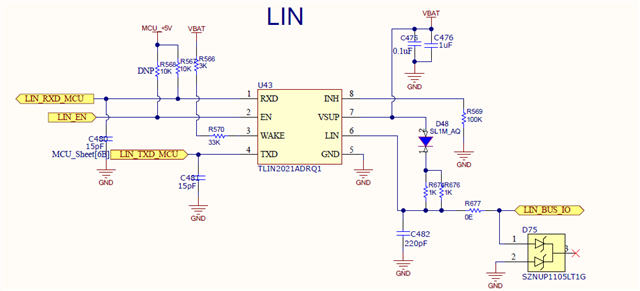
Please review our circuit. Also where to add ferrite and capacitor as per your earlir post. on VBUS line.
Hi Manoj,
Please see my feedback below:
Outside of that everything else looks good.
Regards,
Matt
Corrected Recommendation:
The 100 pF capacitor is appropriate because: (Iam very sorry for in previous post it was my mistake instead 100pf I had write 100nf.)
Recommendation: