Part Number: DS90UB953-Q1
Tool/software:
Electrical Analysis I2C Test
Failed, using the Logic Analyzer to get the I2C signals it show lose communication during the initialization and resetting when the camera connects to ECU Module,
Failed, the LVDS Signals are dropping when the failure presents
- Impedance Test Passed.
- Diode Test Passed
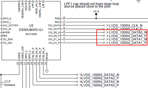
- Voltaje Failed, the DLANE 2 P don’t have voltage (pin 31 CSI_D2P)