LMH0395: Review of the schematic diagram of LMH0395+DS30BA101

Part Number: LMH0395
Other Parts Discussed in Thread: DS30BA101

Tool/software:

Hi TI team,

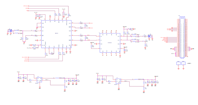
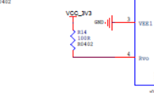
The customer has already applied the LED WALL sending card project, using the application solution made with LMH0395+DS30BA101. Currently, the schematic diagram of this part has been completed as follows. The customer would like to ask the original factory to help check if there are any problems with the schematic diagram. Could you please review it? thank you.

  • Hi Ken,

    US office is closed for holiday 9/1. We will get back to you on 9/2 US time.

    Best,

    J

  • 0 in reply to J

    Hi Ken, 
    Below are the comments for LMH0395:
    1. We recommend 49.9ohm resistor for R11, instead of 37.4ohm.

    Below are the comments for DS30BA101:
    1. 
    Please use 1uF, not 4.7uF and should be placed before this. 

    2. 

    This is not needed for the complement. 
    3. 
    RVO should be 750ohm for 75ohm AC-coupled coaxial cable. 
    4. 
    VCC1 must be connected to 3.3V.

    Best,
    J