This thread has been locked.

If you have a related question, please click the "Ask a related question" button in the top right corner. The newly created question will be automatically linked to this question.

DS90UB935-Q1: TI954-TI935 with 935 AON mode

Part Number: DS90UB935-Q1

Tool/software:

This is the first time we have used 935 internal AON clock  mode.We designed 3 different modules  with 935's AON mode.Both of them 935's GPIO0 output  frame-sync signal for sensor.

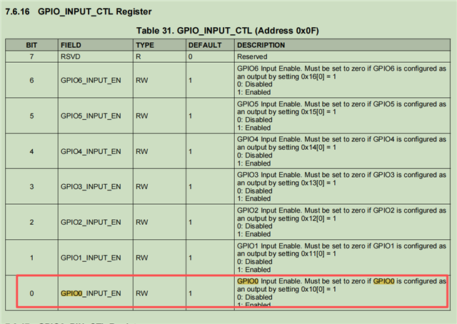
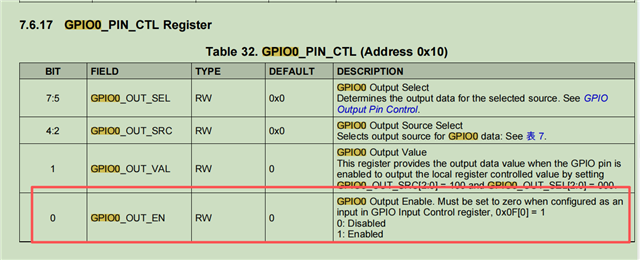
The camera displayed only 6 frame.So we tested the 935's GPIO0 and 954's GPIO0,both of them are 6Hz PWM signals.We controled GPIO0 of 954 disable input,after that,enable 954 GPIO0 output.

However, at CSI-2 Synchronous mode, we can config 935's GPIO0 and 954's GPIO0 as 30Hz PWM pulse .

So internal AON clock affects the configuration of GPIO0? PLZ change GPIO0 to output 30Hz PWM signal.

The following are our configurations.We need your help.THANKS

[ParaList]
//***********configure 954 **************
0xffff,0xFF,//delay 255mS
0xfff8,0x60, // switch device address to 0x60 to configure 954
0xffff,0xFF,//delay 255mS
0x4c,0x01, // Port 0 Writes enabled//
0x5c,0x30, //set 935 Slave Device ID
0x5d,0x44, //set sensor Slave Device ID
0x5e,0xa0,
0x5f,0xb0,
0x65,0x44,
0x66,0xA0,
0x67,0xB0,
0x6d,0x7c, //Configure port to coax mode and FPD III to CSI mode
0x7d,0x01,
0x0F,0x7E, //disable GPIO0 input
0x10,0x91,
0x32,0x01, // csi port0 config enable
0x33,0x03, // 4 lane enable csi for csi port0
0x1f,0x02, // csi speed
0x20,0xE0, //forwarding of RX0 to CSI0
//RX
0x4C,0x01,
0x6E,0xAA,
0x10,0x91,
0x19,0x20,
0x1A,0x8D,
0x1B,0xB8,
0x1C,0x77,
0x18,0x01,
0xffff,0xFF,
0xfff8,0x60,// device address to 0x60 to configure 954
0x58,0x7a, //assert AUTO_ACK_ALL for remote I2C writes to 935
0x5C,0x31, //assert SER_AUTO_ACK for remote I2C writes to 935

//*********** configure TI935 **************
0xffff,0xFF,//delay 255mS
0xfff8,0x30, //// switch device address to 0x30 to configure 935
0xffff,0xFF,
0x05,0x0B //Open internal AON CLK
0x03,0x13 //add
0x01,0x01 //add
0x01,0x03, //RST
0x02,0x73, //Continuous Clock 4-line I2C 1.8V
//0x03,0x10, //CSI-2 Non-synchronous external clock Mode
0x32,0x89, //I2C Pass-Through All
0x06,0x6a,
0x07,0xf2,
0x0E,0x3c, //GPIO HIGH
0x0D,0xd0, //GPIO HIGH
0x05,0x38, //Internally generated OSC clock

//***********configure 954 **************
0xffff,0xFF,//delay 255mS
0xfff8,0x60, //switch device address to 0x60 to configure 954
0xffff,0xFF,//delay 255mS
0x58,0x5A, //deassert AUTO_ACK_ALL now that 935 AON config is complete
0x5C,0x30, //deassert SER_AUTO_ACK now that 935 AON config is complete

//*********** configure TI935 **************
0xffff,0xFF,
0xfff8,0x30, //Ser SlaveID 0x30
0xffff,0xFF,
0x0e,0x30,
0x02,0x73
0xffff,0xff
0x0d,0xd0,
  • Hello, 

    Due to US public holiday, support will resume on Tuesday, September 2nd. Thank you for your patience. 

    Regards, 

    Logan

  • Hi John,

    Thanks for reaching out with this question. In this case the difference could be that the back-channel rate in AON / non sync mode is 10Mbps rather than 50Mbps in sync mode (defined in register 0x58). Frame sync is dependent on the back channel clock, so if the back channel rate has changed the FS low and FS high times also will need to be changed.

    Have you tried to update the FS_LOW and FS_HIGH registers for the two different back channel rates?

    Best,

    Thomas

  • Hi Thomas,

    Thank you very much for your technical support,I change 954's register 0x58=0x5A to 0x58=0x5E,the FSYNC becomed 30HZ. and the camera displayed 30fps.However, the camera is not working stably. It stops generating images after displaying for several minutes. How should I solve this problem?

    Now we use  935 AON  mode(CS1-2 Non-synchronous-FPD-Link lllClock reference derived from internalAON clock.),howerver,954 0x58=0x5E[2~0=110] is for  50 Mbps (default for DS90UB953 CSl Synchronous backchannel compatibility),Are they compatible?

  • Hi John,

    In this case the 0x58 register should still be left at 0x5A, but the FS low and high times should be adjusted accordingly to match 30Hz. 

    Have you read back any diagnostics when the video issue is observed? 0x4d,0x4E,0x55,0x56,0x7A, and 0x7B are a good place to start. Please read these registers back twice when the error occurs (once to read any sticky flags & second time to see if they're still asserted).

    Best,

    Thomas

  • Hi Thomas,

    In 935's AON mode,how should I configure the 954 GPIO0 to output 30Hz pulses ?

    Configured  954 0x58=5A,the camera display 6fps,in this situation, I read the relevant registers.

    935 register unchanged:

    0x4D=00,0x4E=00,0x55=00,0x56=00,0x7A=E4,0x7B=00;

    954 register unchanged:

    First 0x4D=33 changed to 03,0x4D=03 unchanged;

    First  0x4E=6D changed to 0C,0x4E=0C unchanged;

    0x55=00, unchanged

    0x56=00,unchanged

    First  0x7A=0F changed to 00,0x7A=00 unchanged;

    First  0x7B=76,changed to 00,0x7B=00 unchanged

  • Hi John,

    With the 10Mbps back channel rate the below settings should be used for registers 0x19,0x1A,0x1B, and 0x1C.

    Best,

    Thomas

  • Hi Thomas,

    I just returned from a business trip. I'm sorry for the late reply.I modified the 954 register to the following configuration

    0x58=0x5E,
    0x19=0x15,
    0x1A=0xb3,
    0x1B=0x15,
    0x1C=0xb2,

    However,there was no improvement. Now there is a situation where the camera fails to start.

    When initializing 935, if the write operation of 0D=D0 fails, the camera will fail to start.Up to now, I have conducted 153 tests, and among them, there were 8 failures.

    Through the oscilloscope test, I found that if the write operation of 0D = D0 failed, GPIO0 of 954 would no longer output 30Hz PWM pulses; instead, it would output a low level. This is the direct cause that leads to the failure of the camera to start.

    Could you please explain the reason for this situation? Also, could you help optimize the register configuration?

  • Hi John,

    It's important to write to register 0x0E here, but register 0x0E should be okay to keep as remote enable for GPIO pins (might be updated for other GPIO based on use case). Register 0x0E is the GPIO output enable, if this register is not written it would result in the GPIO pin showing constant low.

    In this case there may be NAKs occurring when communicating with the serializer over remote I2C. Could you check if there are errors which accumulate in registers 0x55 and 0x56 of the UB935?

    Best,

    Thomas 

  • Hi Thomas,

    I will check  0x55 and 0x56 of the UB935,but the camera fails to start, I am unable to access the I2C of 935.

    How to access the I2C of 935 in the debug mode after powering on?Which registers must be configured?

  • Hi John,

    In the case that the camera fails to start is the serializer inaccessible? In the previous response above my understanding was that lock in register 0x4D showed up as stable even when the camera startup does not occur successfully. 

    Best,

    Thomas

  • For another project. We have followed the previous 954-935 register configuration AON mode, but now the camera will fail to output after working for a period of time.       

    By using an oscilloscope for measurement, it was confirmed that the root cause was that GPIO0 of 954 did not output the triggering signal.

    We just need 935 GPIO0 to output 30Hz pulses to sensor,but 954 and 935 output 150Hz pulses.

    Please help review the configuration document and look forward to your response.


    954 set
    mclk =25
    avdd =1800
    dovdd =1800
    dvdd =1800

    //*********** diser TI954 config **************
    0xffff,0xFF,
    0xfff8,0x60, //954 SlaveID
    0xffff,0xFF,
    0x4c,0x01, // Port 0 Writes enabled//
    0x58,0x9e, //enable pass throu I2C Pass-Through to Serializer if decode matches 0: Pass-Through Disabled 1: Pass-Through Enabled
    0x5c,0x30, //7-bit Remote Serializer Alias ID TX_ID
    0x5e,0xa0,
    0x5f,0xb0,
    0x66,0xA0,
    0x67,0xB0,
    0x6d,0x7c, //Configure port to coax mode and FPD III to CSI mode
    0x7d,0x01,
    0x0F,0x7E, //disable GPIO0 input
    0x10,0x91,//configures 954 GPIO0 to output the FrameSync signal
    0x33,0x03, // 4 lane enable csi for csi port0
    0x1f,0x02, // csi speed
    ;0x21,0x14,
    0x20,0xE0, //forwarding of RX0 to CSI0
    //RX
    0x4C,0x01,
    0x6E,0xAA,
    0x58,0x5E,
    0x19,0x05,//FS_HIGH_TIME_1, 1333
    0x1A,0x35,//FS_HIGH_TIME_0
    0x1B,0x07,//FS_LOW_TIME_1, 2000
    0x1C,0xd0,//FS_LOW_TIME_0 25hz
    ;0x18,0x00,//FrameSync disable
    0x18,0x01,//FrameSync Enable
    0x58,0x7a, //assert AUTO_ACK_ALL for remote I2C writes to 935
    0x5C,0x31, //assert SER_AUTO_ACK for remote I2C writes to 935

    //*********** ser TI935 config**************
    0xffff,0xFF,
    0xfff8,0x30, //935 SlaveID
    0xffff,0xFF,
    0x05,0x0b, // Open internal AON CLK
    0x03,0x13 //add
    0x01,0x03, //RST
    0xffff,0xff,//delay 256mS
    0x02,0x73, //Continuous Clock 4-line I2C 1.8V
    0x32,0x89, //I2C Pass-Through All
    0x06,0x6a,
    0x07,0xf2,
    0x0E,0x3c, //GPIO HIGH
    0x0D,0xd0, //GPIO HIGH
    0x05,0x38, //Internally generated OSC clock

    //********************** diser TI954 config **************
    0xffff,0xFF,
    0xfff8,0x60, //954 SlaveID
    0xffff,0xFF,
    0x58,0x5A, //deassert AUTO_ACK_ALL now that 935 AON config is complete
    0x58,0x5E, //deassert AUTO_ACK_ALL now that 935 AON config is complete
    0x5C,0x30, //deassert SER_AUTO_ACK now that 935 AON config is complete

  • Hi John,

    It looks like your back channel rate defined in register 0x58 is changing between 0x5E and 0x5A. This will change the back channel rate, and with the frame sync based on the BC clock this can also result in the change in frame sync rate. If you leave the 0x58 setting as 0x5A, the 30Hz frame sync should be seen.

    Best,

    Thomas

  • Hi Thomas,

    The previous 0x18 register existed before the synchronization signal configuration. I just need to move 0x18 to the front of the synchronous signal configuration. Our camera module has been operating continuously at 85 degrees Celsius for 66 hours without any issues. Thank you very much for your support. It helped us solve the problem.