A related question is a question created from another question. When the related question is created, it will be automatically linked to the original question.
If you have a related question, please click the "Ask a related question" button in the top right corner. The newly created question will be automatically linked to this question.
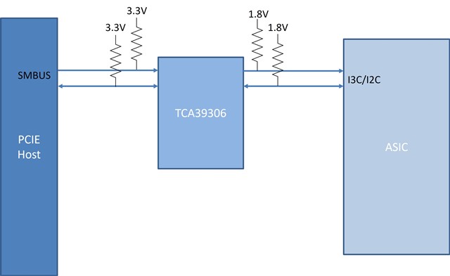
TCA39306 can level translate I3C signals at 12.5 MHz. It is a purely passive device with no digital, it will not recognize I3C traffic.
This device will level translate according to the block diagram, but it does not buffer. 1.8V to 3.3V is a valid use case for this device, external PU resistors are required on both sides of the level translator for it to work.
Sorry for the delay in response - was out of office past few days.
So, if I implement the design with pull-ups (as shown in the attached block diagram), similar to the application example in the datasheet, will I3C communication work reliably for 3.3V to 1.8V translation?
And is there any proper I3C compatible device for my application that you would suggest?
This should work as long as the traces are kept to a minimum and target devices are limited. I3C doesn't have much of a capacitive budget limited to 50pF.
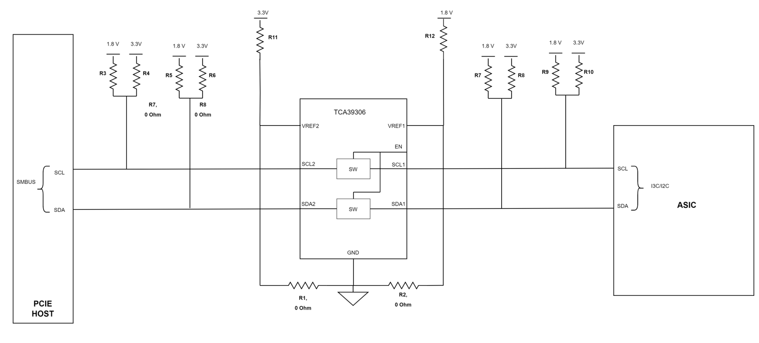
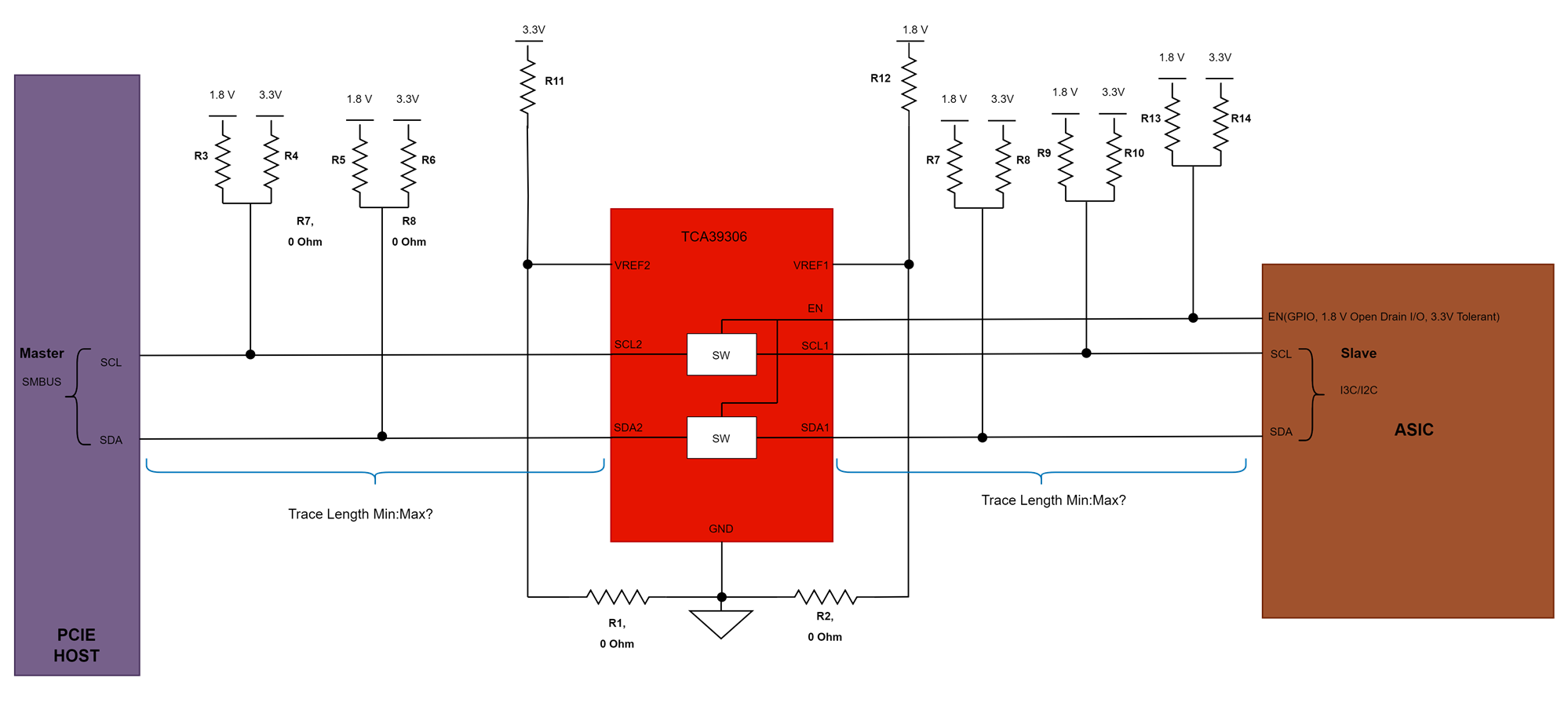
Enable will be controlled by GPIO in ASIC which is 1.8 V Open Drain I/O, 3.3V Tolerant PIN. So based on our use cases we will populate resistors R13,R14 for 1.8V or 3.3V.
Attached updated block diagram:
Pls note: Shifted location of VREF1 and VREF2 in TCA39306 for 3.3V to 1.8V translation
PCIE Host is Master and ASIC have slave interface.
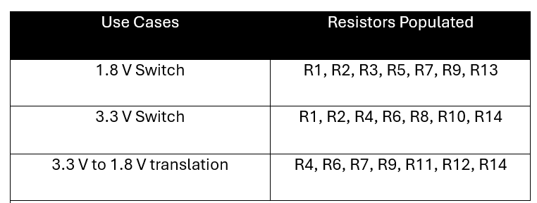
Resistors populated for each use cases is given below:
Questions:
Will this implementation work properly for I3C switching and translation?(Our ASIC is based on MIPI I3C v1.1)
What should be the min:max trace length from Host bus to TCA39306 and from TCA39306 to ASIC?
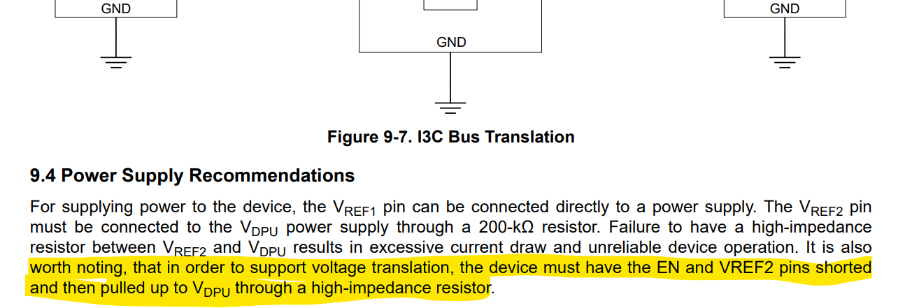
As per application example provided in datasheet related to I3C translation, it is mentioned that EN and VREF2 PIns should be shorted, is it required?
Is there any proper I3C device( MIPI I3C v1.1) available in TI for my application?
Will this implementation work properly for I3C switching and translation?(Our ASIC is based on MIPI I3C v1.1)
TCA39306 is compatible to the I3C spec but may not be entirely compliant to the MIPI I3C spec. For example, the PU resistors required on both sides of the level translator are always ON. Therefore in push-pull mode there will be a constant current sink when the nFET pull-down transistor is ON.
The TCA39306 works for level translating I3C signals, but in not the most efficient way.
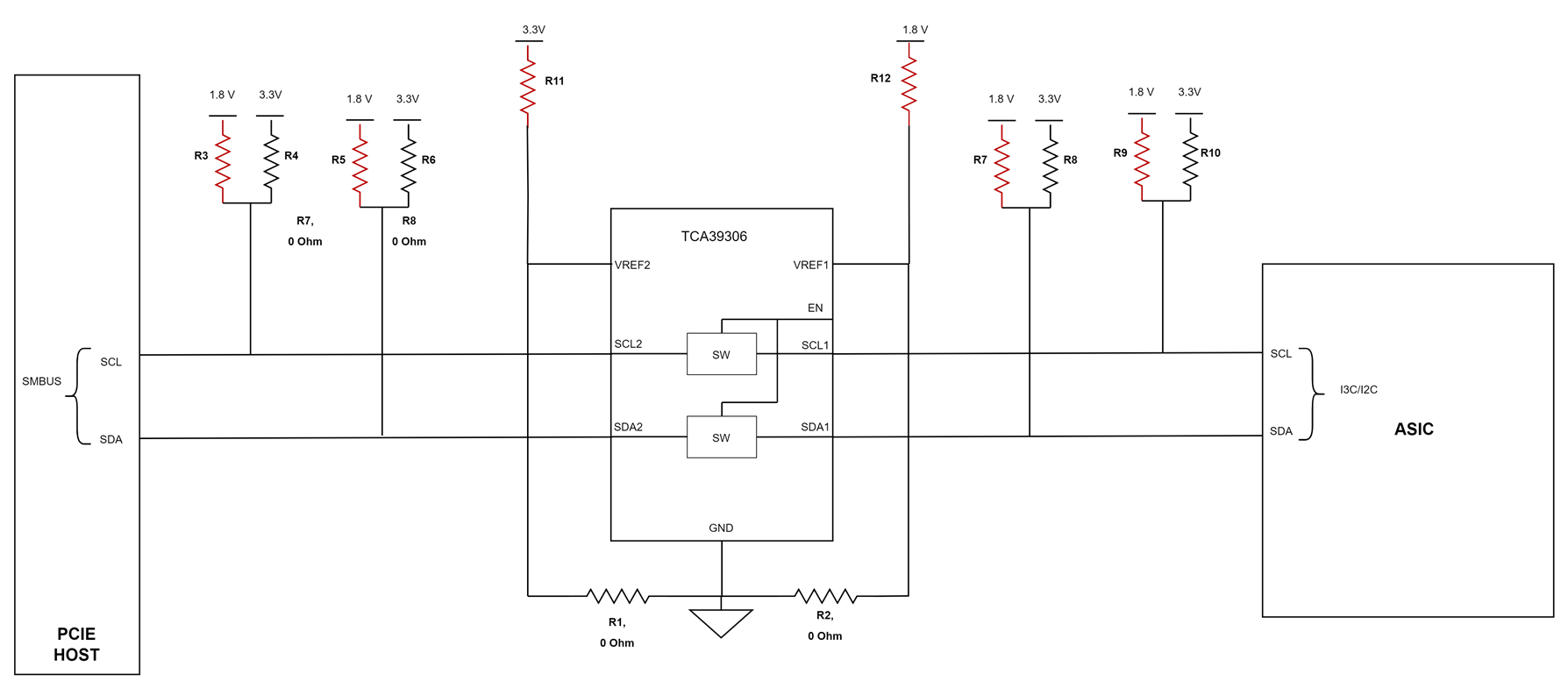
The 1.8V switch use case makes sense.
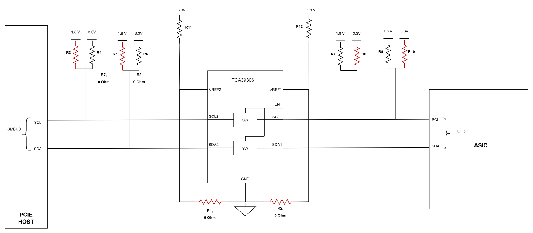
The 3.3V switch use case makes sense.
The 3.3V and 1.8V level translation case will not work. Populating R14 which is the PU resistor to 3.3V means that EN = 3.3V. This sets the gate bias too high. Gate - SCL1 or SDA1 voltage = 3.3V - 1.8V = 1.5V > VTH of the passFET. You create a voltage divider between side 1 and side 2 from the 3.3V supply through the PU resistors, through the passFET, through the PU resistor to 1.8V.
For the voltage translation case, you would need to follow figure 8-1 which is the normal setup for voltage translation, as the EN+VREF2 pin short automatically sets the EN pin to the proper level translation voltage.
if you continue in switch mode by biasing the EN pin manually, you would need to use the 1.8V supply. Instead of populating resistor R14, I would recommend populating R13 in the voltage translation case. You will take a hit on propagation delay because the gate voltage is smaller which means Ron is larger, but level translation should work in that case rather than creating a voltage divider between the two supplies.
What should be the min:max trace length from Host bus to TCA39306 and from TCA39306 to ASIC?
This is hard to tell. MIPI spec has 50 pF of trace capacitance budget. If you take CON from the TCA39306 as a max of 12.5 pF, and the input cap from the ASIC and and PCIE host at ~8pF, then you are left with 21.5 pF of trace capacitance. I would estimate that the maximum amount of trace you can now place is 21.5 pF worth which If I estimated at 1 cm / 1 pf, then you would have 21.5 cm of trace distance you can utilize on the entire I2C/I3C bus segment.
As per application example provided in datasheet related to I3C translation, it is mentioned that EN and VREF2 PIns should be shorted, is it required?
This is not required in the switch mode. If you are following the voltage translation connection example in figure 8-1 of the datasheet, then this is the proper implementation of VREF2+EN short through a 200k PU to VCC2 supply.
Prop delay will be slightly affected (a few ns). The rise-time on the output side of the TCA39306 will be mostly by the PU resistance. We need to ensure that rise-time for I3C is being met on output side which is a direct result of the PU resistance and trace length on output side.