DS160PT801X16EVM: How to fine tune in GUI and definitions

Part Number: DS160PT801X16EVM
Other Parts Discussed in Thread: DS160PT801

Tool/software:

Hi Tech team ,

Here is Sparkle.Co

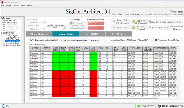
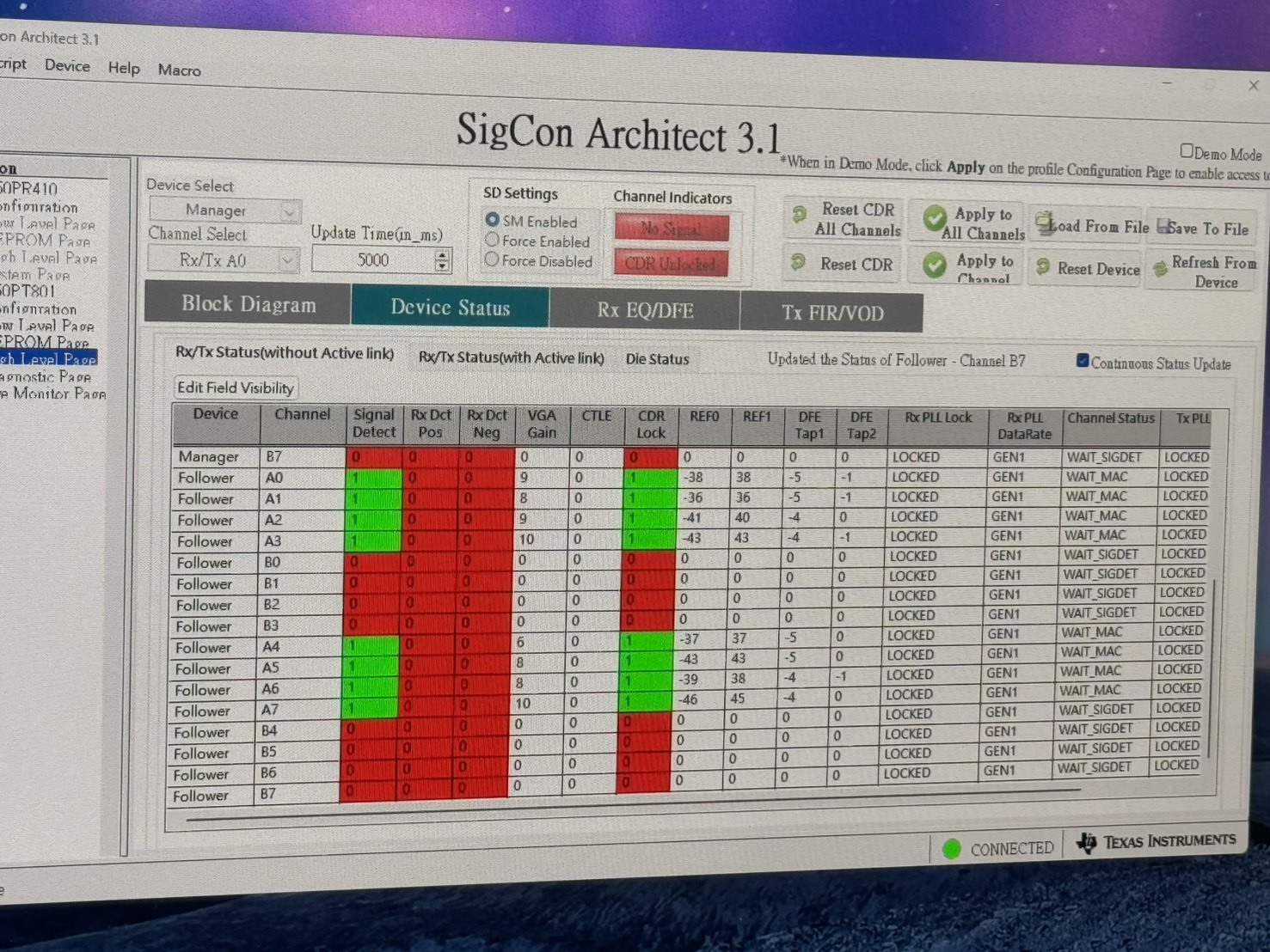
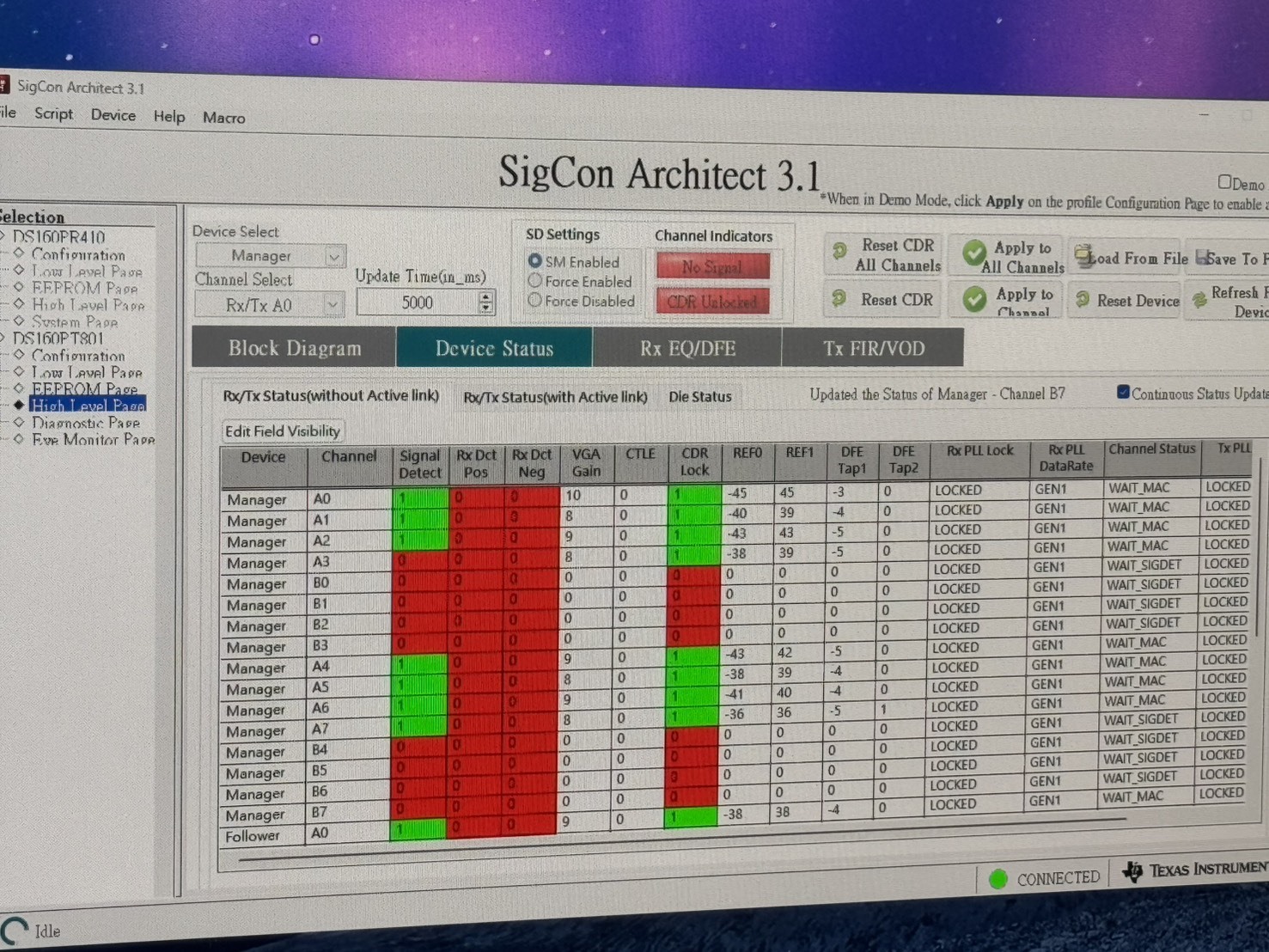
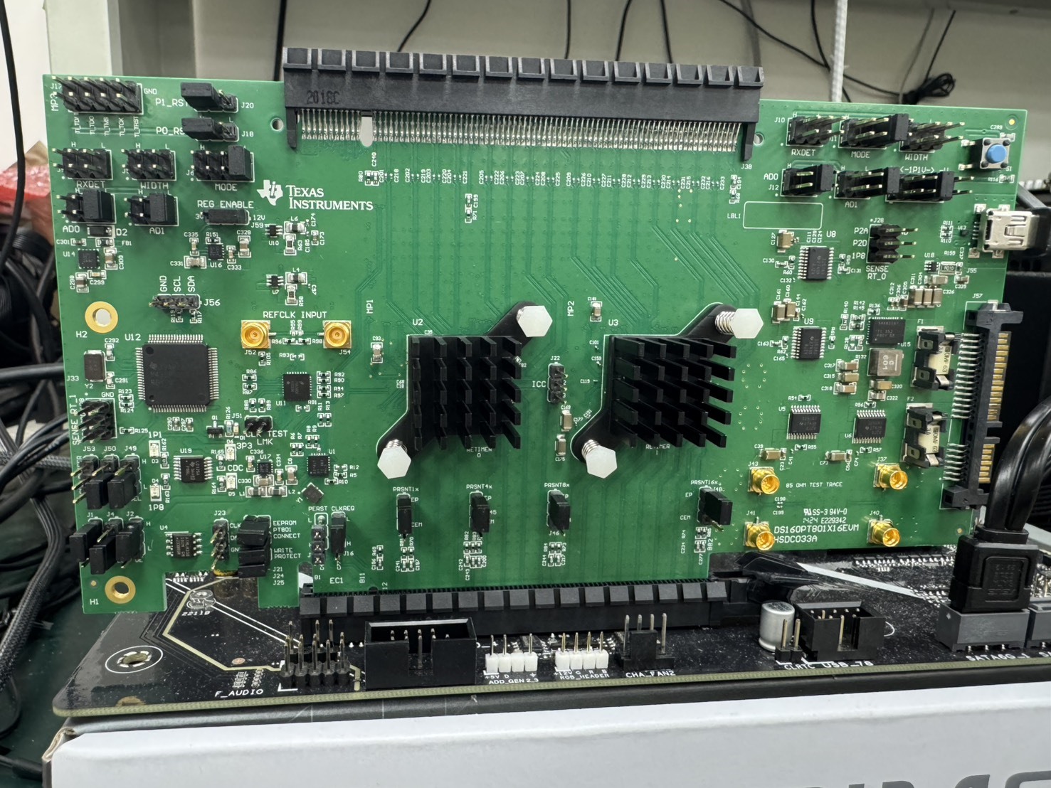
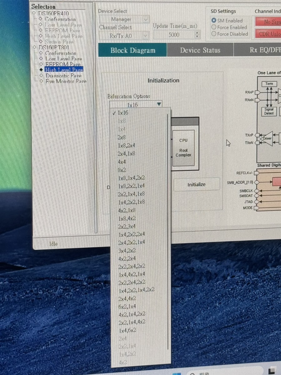
We have installed the GUI successfully and are able to connect to the EVM board. However, we are not sure how to fine-tune the configuration or how to measure the eye pattern. Is there any possibility that you could provide a live stream to teach us how to tune these parameters in the GUI and explain the definitions of those parameters? Since we do not have any technical support available here in Taiwan, we would greatly appreciate it if you could support us with a live stream or remote session.

  • Hi Ken,

    We unfortunately do not have availability this week for a call, but I can give you feedback on your points:

    However, we are not sure how to fine-tune the configuration

    The retimer's signal conditioning systems (CTLE, DFE, CDR, etc.) are automatically controlled and optimized. So manual "fine tuning" usually leads to worse results than the automatic control and we only do a limited amount of it in special cases. Generally speaking, if the retimer is configured with the correct EEPROM to allow the PCIe link to be formed correctly and there are no protocol issues, then the SI performance observed is close to the limit of what is possible in the setup.

    or how to measure the eye pattern

    The GUI has an "eye monitor" page that provides some eye diagram information. When the link is up, you can select a retimer, select a channel, and run "single capture" or "continuous capture" to estimate the eye diagram at the retimer transmitters. However, the most generally useful eye diagram is at the final PCIe receiver, such as the CPU receiver eye diagram, so if you have the appropriate software from Intel or AMD then that can be run on the platform side separately from the retimer or the retimer GUI.

    Best,

    Evan Su

  • Hi Evan,

    Thanks for the quick reply. According to what you mentioned, “manual fine tuning usually leads to worse results”, does that mean we only need to write the basic configuration (DS160PT801_EEPROMImage.hex) file downloaded from your website? We have already written the file DS160PT801.hex to our EVM board, but after doing so, I cannot see any difference in the EEPROM table when reading it back from the EEPROM. We would like to clarify the following points:

    1. To make the Gain or EQ work properly, do we only need to write the EEPROM with the provided hex image file?

    2. How can we ensure that the EEPROM is written correctly? Do we need to configure any additional settings in order to complete the write process?

    3. We are currently facing an issue: when installing the graphics card as the end device, it can be detected under Device Manager and the driver installs without issue, but we are unable to scan the eye pattern for the follower device. It always shows CDR unlocked and No Signal. However, when checking the status under the High-Level Page, the follower shows the correct data rate as GEN4, but we are able to scan the eye pattern for the Manager device .

    I think it is a little difficult to explain everything in text since we are not experts in this area. Could we schedule a call next week, or at a time that is convenient for you? We would greatly appreciate it if you could provide live stream instructions. Thanks!

  • Hi Ken,

    To make the Gain or EQ work properly, do we only need to write the EEPROM with the provided hex image file?

    Gain and EQ are automatically controlled by the retimer and nothing in the premade EEPROMs that we distribute (I assume you got the file from the DS160PT801_EEPROMImage ZIP folder) will affect them. There is a README file inside the ZIP that has instructions on which EEPROM file to pick based on your link width or other factors. The EEPROM on the EVM may already be flashed with something from the factory, probably the generic DS160PT801.hex, so if you didn't observe any difference that's likely the reason.

    How can we ensure that the EEPROM is written correctly? Do we need to configure any additional settings in order to complete the write process?

    I haven't seen any issues with EEPROMs not being written correctly. The programmer in the SigCon Architect GUI works pretty well overall. If you use the "Read from EEPROM" function and the contents load correctly, then very likely the data is fine. If there is a problem (corrupted or format is incorrect) then it will tell you.

    We are currently facing an issue: when installing the graphics card as the end device, it can be detected under Device Manager and the driver installs without issue, but we are unable to scan the eye pattern for the follower device. It always shows CDR unlocked and No Signal. However, when checking the status under the High-Level Page, the follower shows the correct data rate as GEN4, but we are able to scan the eye pattern for the Manager device .

    What is the link width of the graphics card? If it is less than x16, then some channels in the retimers will not be used and those will not have any signal. In the High Level Page you can check the status of all channels in both retimers.

    When you want to look at the eye diagram in the Eye Monitor, you should double check the device and channel selections to make sure you are looking somewhere that is supposed to have a signal.

    Best,

    Evan Su

  • Hi Evan , 

    Is it normal that when connecting an end device, such as a PCIe Gen4 x8 graphics card, the device's signal and CDR check are never able to turn green? 

  • Hi Ken,

    That looks kind of strange. Channels A0-A3 and B0-B3 in the follower retimer are showing that the PLLs have been locked but they are waiting for signal. It's possible there could have been some activity during startup but the signal and terminations stopped for some reason, or maybe the retimers were expecting a different link width from what actually exists in this setup. Have you checked the PCIe link width of the graphics card to make sure it is linking up in the correct x8 width?

    Best,

    Evan Su

  • Hi Evan,

    I have checked with GPU-Z and confirmed that the PCIe link width is running at Gen4 x4, and the EEPROM is using only the basic hex file. It also states that the width is determined by the Width pin (what does this mean?). The EVM board is installed in a PCIe slot that supports Gen5 x16.

    I have checked the EVM datasheet, but it seems there is no description about the J9/14 Width pin header. Currently, it is left floating, which is the default setting that results in the width being set to 4x4.

    I have also noticed that when installing the graphics card with the retimer, especially in PCIe slot 1 controlled by the CPU , the VGA card sometimes fails to pass the POST phase during boot-up, although occasionally it does succeed. When switching to another platform, the issue occurs on both the CPU- and PCH-controlled PCIe slots. However, when testing with a platform using a Core Ultra CPU, everything works fine.

     I have tried setting the PCIe generation to Gen4 or Gen5, enabling Secure Boot, and disabling Fast Boot, but none of these helped. It seems like there may be a link training compatibility issue with the retimer, or perhaps the EEPROM needs to be edited for the startup process. Could it also be related to the follower always waiting for a signal to be received?

    P.S. I have confirmed that with the graphics card attached to both the CPU- and PCH-controlled PCIe slots, I can reboot 20 times consecutively without any issue.

  • Hi Ken,

    The WIDTH pin and its settings are explained in the full DS160PT801 datasheet, which is not public on TI.com. Have you requested access to the DS160PT801 secure resources using the link on the DS160PT801 product page?

    I have also noticed that when installing the graphics card with the retimer, especially in PCIe slot 1 controlled by the CPU , the VGA card sometimes fails to pass the POST phase during boot-up, although occasionally it does succeed. When switching to another platform, the issue occurs on both the CPU- and PCH-controlled PCIe slots. However, when testing with a platform using a Core Ultra CPU, everything works fine.

    I have not heard of this before.

    • What is the "VGA card"? Same or different from the graphics card?
    • How is the POST test failing? VGA card cannot be detected at all, or a different symptom?

    Sometimes we have found that the DS160PT801 doesn't get along well with certain CPUs or endpoints, but this is not uncommon for retimer applications and it is related to some timing or protocol differences, possible to adjust slightly in EEPROM but difficult to debug. For now I would focus on correcting the link width to the intended Gen 4 x8.

    Best,

    Evan Su

  • Hi Evan,

    I and Ken have tried connect J9/J14 WIDTH pin to both pull high to PWR with to 10kohm. But seems can't work.


    1. Some of signal detect still "0", is it normal? 

    2. RxPLL datarate only show Gen1, can't run at Gen4 data rate. How to fix it?

    3. For J45–J48, do we need set all floating, only connect J46 pin2-3 for set PRSNT pin to x8?

    4. Is there have x8 EEPROM .hex can share to us?

    We can't find 1x8 image in secure resouce folder. 

    And also can't choose 1x8 setting in high level page to generate 1x8 EEPROM iamge.

    5. Is there any sample code if we need configurate from BIOS via I2C? 

    Thanks!

    Jeff