This thread has been locked.

If you have a related question, please click the "Ask a related question" button in the top right corner. The newly created question will be automatically linked to this question.

DP83867IR: Practical Debug How To

Part Number: DP83867IR
Other Parts Discussed in Thread: AM62L

Tool/software:

Hello.

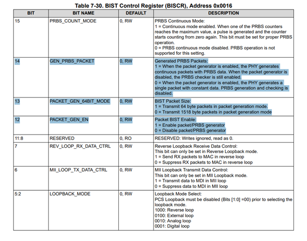
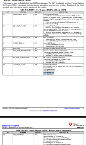
We currently have some issues with your Ethernet PHY DP83867IR and trying to troubleshoot it. And as it is hardly possible to measure the signals under the SoC for the RX lines, I would like to try to use the internal self test. I also found your APN for that, which roughly explains what to need to be done. 

And here is my question: Is there an APN which actually explains how this is done in form of an example? Like what commands do I need to send, to the PHY? How do I check that the receiving packets are the same? Or can I just do an iperf command on myself?

Maybe you have something more practical which you are willing to share.

Cheers

  • Hi, 

    Typically, we use packet generators and connect the board to the packet generator from Spirent. However, the hardware could get expensive. As a cheaper solution, ping or iperf command may work, but you may also want to try packETH to generate packets with the same packet content. 

    Best,
    J

  • I tried it with iperf once, but with no success, as no link was established. And you kind of would need to ping your own address, which, AFAIK, will always succeed.

    I will need to look into the packetETH if we need to compile it. As we want to check the connection of the AM62L to the PHY. I think this would also be the showstopper for the Spirent packet generator, as it looks like, that it is Windows software.

  • Hi, 

    packetETH may work to send continuous streams of packets. Spirent packet generator is a hardware tool that generates packets for the link partner. As it is a hardware tool, this may be add up quite a bit on the cost. 

    Best,
    J

  • So "may" means, you didn't test that?

    The Spirent packet generator would also be unintersting, as we might have issues with the AM62L or the DP RGMII Interface, so with the additional hardware, we wouldn't find the error.

  • Hi, 

    My team uses a packet generator hardware to connect our boards and run our tests. The packet generator acts as a link partner that can continuously generate packets onto our DUTs.

    The additional hardware will also work as you can test the RGMII receiving path of the board, which I thought was your initial issue. 

    Best,
    J

  • I would like to test both the RGMII TX and RX between the SoC (AM62L) and the PHY (DP8something). Issue is, that you can hardly measure the RX lines as you can't connect under the AM62L. And currently we have an issue with the performance, as it is fairly low.

  • Hi, 

    You can use MII loopback to loop the packet coming from the MAC back to the MAC. 
    What exactly is the issue you are facing here? Is there packet losses in the RGMII line? How have you ruled out that MDI side is not an issue?

    Best,
    J

  • OK… but this won’t help me that much, to be honest. My biggest problem with this debug functionality is that I have absolutely no idea how to benefit from it. I’m speaking more about the practical side—like getting a nice scope but without a manual. I do understand that you have some fancy hardware to use it, but it would be nice to have an example to follow along (like in the PHY datasheet to write/read the extended registers).

    Well, there are multiple problems. I am currently in talks with another FAE regarding the IBIS model and the issue that the AM62L has the wrong default driver settings. There is another issue with the PHY itself where two buffers behave differently, resulting in excessively high rise/fall times on these inputs. I did get some commands to help with that, but this won’t solve the issue that I can’t really measure at the AM62L input to verify the signals, as the quality of this measurement is heavily dependent on the position. And as I currently don’t really trust the IBIS model, the debug functionality would have been my second-best solution to verify the RGMII interface.

    As far as we can see, there is neither packet loss nor CRC errors—neither with your fast nor slow settings. The IEEE compliance test is borderline but mostly OK. In some circumstances we get full bandwidth (>900 Mbit/s), but there are also scenarios where we don’t even get 300 Mbit/s, and it is always in the direction from the AM62L to the attached device. It’s kind of all over the place.

    But I think that if I don’t succeed with either of these two tickets, I will create a new ticket to address this particular issue.

  • Hi, 

    I see. As I am Ethernet PHY applications engineer, I suggest to create a separate post to discuss this with the Sitara team. 

    I understand that it is frustrating to probe the MAC side of the signal especially when there is no good way to send packets continuously from the MAC. 
    In terms of rise/fall time, DP83867 has MAC impedance control on 0x0170 which has been known to help with rise/fall time issues.You can change the value on this to change rise/fall time on the RGMII lines. 


    In addition, if you have another board with 867, you can also enable PRBS packet generation from the 867 and then send packets into the problematic board. This data will be sent to the RGMII RX line at least so you can probe the RX lines of RGMII at least. 


    You can enable bits 12, 13, 14 to 1 to generate 64 bytes continuous PRBS packets to its link partner. 

    You can generate PRBS packets with length of 64 or 1518 bytes. I know you would like to test both TX and RX RGMII lines, so this may not be the most sufficient method for you. However, I hope that this can help you with probing the RX lines more easily. 

    Best,
    J

  • I should have mentioned that rise/fall time are not great on TX lines because of hardware issues in the current AM62L SoC (which will be fixed in the next revision) and the different input buffers of the PHY. I didn't check RX jet, as there is no good connection point (the next best would be at the PHY, which is the furthest one). That's why the approach of the self-test was chosen, in hope to validate it at least in this way, as I also have some concerns about your IBIS model for the AM62L (but this is also another issue).

    Attaching a second board doesn't sound quite right, as you potentially introduce problems caused by a different system. But getting data in the device can also be done with iperf, so this is not the problem.

    As mentioned above, the goal would have been to validate the RGMII interface in (mainly) RX direction on the SoC itself with its own board tools.

  • Hi, 

    We had internal discussion on this and we are thinking that if you put the PHY in analog loopback and then generate PRBS data from the same PHY, this may be able to loop the data back into RGMII RX line. 
    If this doesn't work, you would have to use a loopback cable to send the PRBS data back into RGMII RX line. Otherwise, the best solution would be the one I suggested above. Even though you are introducing additional variable, the above method will definitely be able to send data into RGMII RX line. 

    You can generate PRBS data as I mentioned in the previous post. You can set the PHY in analog loopback by setting bits 5:2 on reg 0x0016 as 0010 and bit 1:0 of the same register to 00. 


    Best,
    J

  • What do you mean with loopback cable? It is 1000BaseT, where till now, I thought that the 4 pairs are bidirectional. (Funnily I ones read otherwise, but can't find it anymore).

  • Well yes, I saw them aswell. But maybe I am missing something and I am heavily outing myself here. AFAIK I have 4 pairs which can send data, hence the 125 MHz CLOCK which equals with DDR to 1 GBit. If I now loopback two pairs, I would have max 0,5 Gbit (theoreticly). And I read something that if it only has two pairs available it would switch to 100 Mbit, which have other timings as 1 GBit.

  • Because these are bidirectional lines, PHY is meant to echo cancel its transmitting signal out to properly receive the receiving signal.