TCAN4550: The application issues of chips

Part Number: TCAN4550

Tool/software:

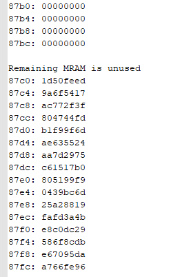
When I was testing can communication here, I soon found that after sending a command to the slave device, there was no data return from the slave device. At this point, I checked the interrupt nINT pin of tcan4550 and found that it was always at a low level. The chip should be abnormal.

The can command was sent 10 times.  From the 0th to the 9th time, the slave device could reply with the data.  After the 10th time, the slave device no longer replied with the can data.

I'm extremely anxious. Please help me figure out what the problem is and how to solve it

  • Hi Jimmy,

    It sounds like you are getting a uncorrected ECC error that is causing the device to re-enter initialization mode (setting the INIT bit of the Control register 0x1018[0] = 1) and stops CAN communication resulting in your CAN Silent error which is then causing the CAN Error and Global Error bits to be set.

    The MRAM cells are not automatically initialized to "0" at power up or following a reset, but the ECC calculations assume all unused bits have a value of "0."  If you are not initializing the buffer cells to zero as part of your configuration sequence, then you will need to make sure to write zeros to any unused bytes in the MRAM elements such as the TX buffers to prevent possible ECC errors.

    Regards,

    Jonathan

  • After reading your reply, it seems that tcan4550 has not re-entered the Initialization mode. There are the following two reasons:

    When initializing the chip, there is a write 0 operation for the entire MRAM as follows:

    void m_can_init_ram(struct m_can_classdev *cdev)
    {
    int end, i, start;

    /* initialize the entire Message RAM in use to avoid possible
     * ECC/parity checksum errors when reading an uninitialized buffer
     */
    start = cdev->mcfg[MRAM_SIDF].off;
    end = cdev->mcfg[MRAM_TXB].off +
    cdev->mcfg[MRAM_TXB].num * TXB_ELEMENT_SIZE;

    for (i = start; i < end; i += 4)
    m_can_fifo_write_no_off(cdev, i, 0x0);
    }

    2..When an exception occurs, the value of register 0x1018 is 0, and bit0 is not set to 1, as follows:

    1018: 00000000
    1019: 00000000
    101a: 00000000
    101b: 00000000
    101c: 00004409

    1464.regdump.txt

    Could you please check it? The above is the register dump

    TCAN4550-SCH.pdf

    Please also check if this schematic diagram is correct. If any modifications are needed, please explain it in detail

  • Hi Jimmy,

    OK.  I will review your register log and schematic for a possible reason for the ECC error and a halt to CAN communication. 

    Have you tried clearing all of the interrupt registers and see if it resumes CAN communication? 

    Is this error repeatable and always occurs on the 10th frame?

    Do you have more than one board or TCAN4550 device and if so have you tried the test on multiple units to see if the issue may be specific to the device which means it may have a defect, or whether it occurs on all your devices which means it may be due to a register configuration issue?

    Regards,

    Jonathan

  • this error is repeatable,but no always occurs on the 10th frame,it is random.
    We have encountered this issue on multiple devices during testing.

    register log and schematic,Have you found any problems?

  • Hello Jimmy and Wang,

    I'm not sure what value you are using for TXB_ELEMENT_SIZE, but if it is not 18 then you may not be completely initializing all of the allocated MRAM to zero based on my understanding of your initialization sequence.  A TX Buffer Element has 2 header words (8 bytes) + the number of bytes allocated from the TX Buffer Data Field Size register (TBDS in register 0x10C8[2:0]).  Currently you have a 64 byte data field which is 16 words. 

    If you are by chance using 16 or 18 for the TXB_ELEMENT_SIZE to verify if you are possibly not initializing all of the TX Buffer/FIFO memory. 

    From your configuration, it appears you are using about 97% of your MRAM and you only have 16 words of unused MRAM that is not being initialized.  I would recommend to initialize all MRAM (0x8000 to 0x87FF) to ensure there is no chance of accessing memory that has not been initialized to zero and take away that possible reason for an ECC error.

    From your datalog, I see that MRAM cells 0x87C0 to 0x87FF are random values that have not been initialized.  Please try to initialize these bytes and see if this resolves your ECC errors.

    From the schematic, it overall looked OK. I don't know what the crystal's load capacitance requirements are, but 22pF caps for OSC1 and OSC2 are about twice the value I normally see for 40MHz crystals.  Because the crystal is directly used by the MCAN controller and the Digital Core, any disruptions to this clock can also cause SPI and CAN communication errors.  In general if the crystal circuit is not optimized, it may fail to start oscillating, stop oscillating, or have disruptions by switching between single-ended clock mode and crystal mode if the oscillation voltage drops below 150mV on OSC2.

    Please also review the TCAN455x Clock Optimization and Design Guidelines Application Report (Link) for more information.

    Regards,

    Jonathan

  • The entire 2K space of MRAM has been initialized to 0, but errors still occur. Attached is a register dump, please help to take a look again. Thank you!

    The MRAM configuration is as follows:

    bosch,mram-cfg = <0x0 0 0 22 0 0 5 5>;

    The code for initializing MRAM to 0 is as follows:

    void m_can_init_ram(struct m_can_classdev *cdev)
    {
    int end, i, start;

    /* initialize the entire Message RAM in use to avoid possible
    * ECC/parity checksum errors when reading an uninitialized buffer
    */
    start = cdev->mcfg[MRAM_SIDF].off;
    end = cdev->mcfg[MRAM_TXB].off +
    cdev->mcfg[MRAM_TXB].num * TXB_ELEMENT_SIZE;

    start = 0;
    end = 2048;
    printk("yjc %s mram clear start:0x%x,end:0x%x \n",__func__,start,end);

    for (i = start; i < end; i += 4)
    m_can_fifo_write_no_off(cdev, i, 0x0);
    }

  • Hello Wang,

    The log file doesn't show there are any ECC errors.

    The CEL field of the Error Counter Register shows there are protocol errors being generated (0x1040[23:16] = 24).  The REC field is also >0 (0x1040[14:8] = 2).

    The MCAN Interrupt register (0x1050) has the following bits set:

    [29] ARA -  This is likely due to your error log creation because you are not limiting your reads to proper register address and are doing a read for every byte instead of every word.  You are also reading from register addresses that are either reserved or do not exist.

    [27] PEA - There are protocol errors in the arbitration phase detected which is also what is causing the CEL counter to increase.  I would suggest verifying the nominal and data bit timing configuration to make sure that it exactly matches the bit timing configuration of your other CAN nodes in your test setup.  Any difference in bit timing configuration can lead to sampling errors and cause this type of error. 

    [12] TEFN - You have a TX Event FIFO entry from a successfully transmitted message

    [11] TFE - The TX FIFO is empty and there are no messages to transmit. 

    [0] RF0N - The RX FIFO 0 has a new message from a successfully received message

    The Interrupt register (0x0820) only indicates a CAN Silent error meaning that there has not been a state change between a dominant and recessive bus level within the approximate 1 second timer.

    I can't really detect any configuration issues from this configuration.  The device is transmitting and receiving messages although some protocol errors are detected but not enough to cause the device to enter a bus off condition.  There are no messages loaded into the TX FIFO so if you are expecting the device to transmit a message, then you may need to determine why the TX FIFO is empty which may be the result of an error in your application firmware.

    If the bit timing configuration settings are the same for all your other CAN bus nodes, then you may need to evaluate the clock frequency of your crystal to make sure it is within the required tolerance.  The crystal's oscillation frequency changes with capacitance, so if the capacitance is too large your frequency will reduce resulting in time quanta that are larger than expected which may lead to bit times being longer than expected which may cause sampling errors with other devices operating on more nominal clock frequencies.  I previously mentioned that your 22pF caps seem larger than I usually see, so you should verify the CAN bits have the expected bit periods with a scope and also you may need to try your tests with different cap values if your caps are too large.

    Regards,

    Jonathan