SN65DSI86: Debug request on SN65DSI86 in system

Part Number: SN65DSI86

Tool/software:

This going to deep for and I need your help. The board schematics needs to be ready next week Tuesday. appreciate your help.

Customer info:

Regarding the SN65DSI86:

In our last state of our carrier board we have designed the board to connect several video bridges to it. We have created a mini PCB with the DSI Bridge SN65DSI86 that is connected to our carrier board. The bridge of the mini PCB currently does not work. The Test picture is shown on the LCD (eDP lines of the bridge works fine) but the DSI communication between the SOM and the bridge has the error flag CHA_DSI_PROTOCOL_ERR is set. The DSI lines of the bridge are directly connected to the AVNET SOM with the IMX.85. If we connect the eval board of the SN65DSI86 to the DSI connector it works fine.


This is the reason why I ask you: can you please review our next design where the TI DSI bridge SN65DSI86 is integrated to the carrier board?

You can find the schematic page attached.

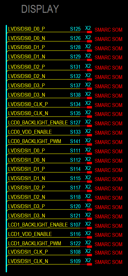
The connection to the SOM via the SMARC interface has the following pinout:


Do you have any other important points regarding the schematic of the bridge?

Would be nice to get a feedback until Tuesday next week from your side, because the schematic has to be finished next week.

----------

It is possible to set-up a call Dallas morning time as the customer is located in Germany. 1st prio is Schematic review. 2nd prio why the min PCB (daughtercard) doesn't work.

  • Hi Frank,

    I will review the schematic and get back to you by Friday.

    For the DSI input video issue, "CHA_DSI_PROTOCOL_ERR" and other 0xF0 - 0xF1 errors could be due to SI issues or DSI protocol setup issues. 

    1. When the DSI source is connected to EVM, is the source set up the same way as when it is tested with the custom board? Is there any issue with the connectors, and layout?


    2. For the DSI86 EVM and DSI86 mini PCB, are both setups programmed the same way? The programming is the register settings done to configure the device.

    Also, please note that the initialization sequence of the device has to be met "8.4.2 Power-Up Sequence".

    Best regards,
    Ikram

  • Hi Frank, 

    1. The schematic you shared has pin number assignments that do no match the SN65DSI86-Q1. Please check the pin assignments for the SN65DSI-Q1 from the datasheet and update the schematic component for this. 

    Is the SN65DSI86 (BGA device) or SN65DSI-Q1 used?

    2. Also, please check that the I2C lines have adequate pullup resistors added. 

    3. For the EN pin, we recommend a 200 nF capacitor, but the value ultimately depends on the customer's implementation.

    4. For the crystal used for the REFCLK, please check the component datasheet to verify that it meets the REFCLK specifications shared in the datasheet.

    Please update the component pin assignments and let us know if there are any questions.


    Best regards,
    Ikram

  • Hi Ikram,

    1. we use the SN65DSI86 (BGA version). Do we have to update the pin assigment with the BGA package?

    2. I2C lines pulled up from the pull ups on the SOM side

    3. EN pin is driven bi a SOM GPIO. I think a capacitor is not necessary in this case, right?

    4. already checked. Can you please double check the spec? We use the EPSON SG-210STF (X1G004171003500)

  • Hi Andreas,

    1. If it's the BGA package then it should be okay, if you checked that the numbers and the BGA grid are matching. The datasheet has the assignments numbered A1 - J9, so you can compare the numbering to the schematic footprint in your design.

    3. Even with the controller GPIO it may be helpful to add a capacitor, but this ultimately depends on your system implementation.

    4. From the datasheet I found online, the specs match the datasheet. Please be sure to use REFCLK frequency mentioned in the datasheet, and also please check the jitter specification. I could not find the jitter specification.


    And regarding the system bringup, we shared the below information: 

    The E2E has the programming tools for the DSI86: https://e2e.ti.com/support/interface-group/interface/f/interface-forum/1382976/faq-sn65dsi8x-programming-tools

    If there are issues with the driver, you could also try using the calculator tool to get the register settings. This will be based on the DSI and eDP settings, and resolution and timings used for the display. You can program the device via I2C to work with color bar (for testing) and for DSI input.

    Since the current setup is working with the color bars test pattern, there could be an issue with DSI timings mismatch. Are the DSI clock lanes speed, and programmed timings matching the programming for the DSI86?
    After initialization, please clear 0xF0 – 0xF8 and then read again during runtime. This will clear any spurious errors during startup. Then please check these registers for errors again for both EVM and mini PCB.


    Best regards,
    Ikram