TUSB211A: TUSB211A layout routing question !

Part Number: TUSB211A
Other Parts Discussed in Thread: TUSB211PICO-EVM

Tool/software:

Hi Sir,

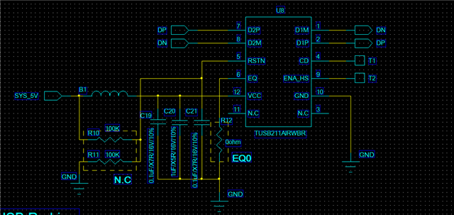
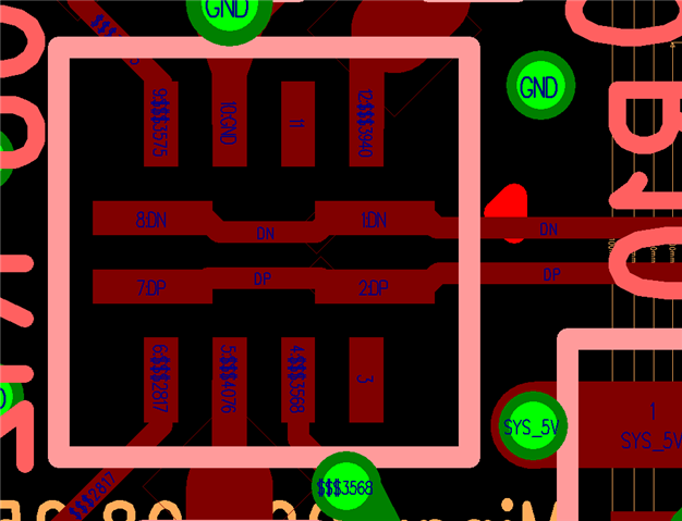
           If  TUSB211A  D+/D- input and output at the same side, this trace routing is correct ?

            Please see below :


  • Hello,

    What is your routing here? Are you intending to just have the signal go in and come back out of the redriver then go back into the USB2 lanes?

    I believe this routing should be possible, our TUSB211PICO-EVM uses the same type of routing in its EVM for the same type of application, though it is mean to to be added to an existing layout: www.ti.com/.../TUSB211PICO-EVM 

    My main concern is the USB2 routing, and whether there would be any reflections. Typically, I would recommend having the signal go through the redriver if possible.

    Thanks,

    Ryan

  • Hi Ryan Sir, Routing is USB1 DP/DN --> TUSB211A --> USB DP/DN output.  Base on my ideal design the signal is  through redriver when output, but PCB space is not enough  , so it is output the same side. Currently,  USB connect device is UVC Camera, base on this condition,  Can you provide suggestion for me ?

    schematic below -->

  • Hi Lee,

    Typically the TUSB211A footprint is considered pretty small, especially because it can be placed directly over the TUSB2 trace, you just have to make the space for the resistors and capacitors.

    If there is no way to make that work, and you have to make it work like this, then I don't believe there are any issues. I would just make sure this layout does not strongly affect the signal.

    Assuming both R10 and R11 are DNP, I don't have any issues with this schematic or layout.

    Thanks,

    Ryan

  • Hi Ryan Sir,

             Understood, thanks !

    Len