This thread has been locked.

If you have a related question, please click the "Ask a related question" button in the top right corner. The newly created question will be automatically linked to this question.

DS90UB960-Q1: Configuration for Ti960+Ti953

Part Number: DS90UB960-Q1
Other Parts Discussed in Thread: TDES960, DS90UB953-Q1, TSER953, , ALP, USB2ANY

Tool/software:

Hi Ti team,

We need two configurations for Ti960+Ti953, can you provide it?

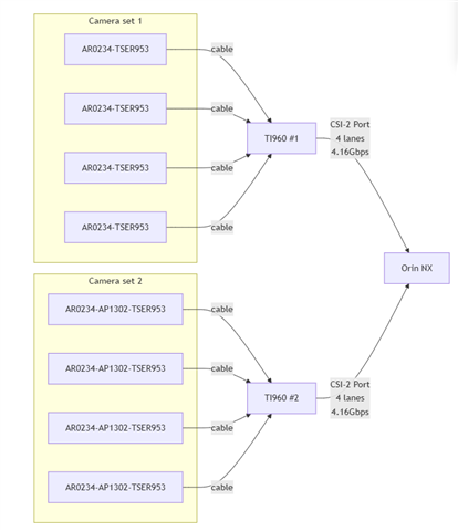
configuration1:One Ti960 is connected to four Ti953 devices. The data format of the sensor(AR0234) output is 4lane raw10, vc-id=0.

                        The output of Ti960 is 4.16G, 4lane.Use virtual id to distinguish the four sensors.

configuration2:One Ti960 is connected to four Ti953 devices. The data format of the ISP(AP1302) output is 4lane Yuv422(8bit),vc-id=0.

                        The output of Ti960 is 4.16G, 4lane.Use virtual id to distinguish the four sensors

Also, Please provide the configurations for the two synchronization methods.

1.We used external SYNC from GPIO7 of Ti960, and output from GPIO0 of Ti953

2.Use Ti960 internally generate a FrameSync signal 25FPS(Please provide the method for calculating frequency,We will employ multiple frequencies),and output from GPIO0 of Ti953
  • Hi Zhang,

    Can you answer the following questions to help me create a configuration script?

    • Are you using FPD-Link devices DS90UB960-Q1 and DS90UB953-Q1 or V3Link devices TDES960 and TSER953?
    • Do the sensor and ISP CSI-2 outputs use continuous clock?
    • What is the data rate per lane of sensor and ISP CSI-2 outputs?
    • Is an external oscillator used in camera modules?
    • Is 953 CLK_OUT feature needed to provide a reference clock to sensor and ISP devices? If yes, what clock frequency is needed?
    • Note that 4.16Gbps is the max supported data rate of the forward channel (953 output / 960 input). Is this the intended data rate of the forward channel? Note that there is some dependency on oscillator frequency.
    • Do you intend to use synchronous or asynchronous clocking mode for the link between 960 and 953?
    • What forwarding method do you intend to use with the 960? The following synchronized forwarding methods are supported: basic sync, line-interleaved, line-concatenated.
    • When internally generated FrameSync signal is used, what high/low duty cycle do you intend to use? (for example 50% high / 50% low)
    • Should the 960 output come from CSI port 0 or CSI port 1?
    • What data rate per lane do you intend to use for the 960 CSI-2 output? Note that 960 supports up to 1.664Gbps per lane but there is some dependency on oscillator frequency.
    • Do you intend to use skew calibration (initial or periodic) on the 960 CSI-2 output? Note that this is usually recommended when the output data rate per lane is greater than 1.6Gbps.
    • Should continuous clock be used on the 960 CSI-2 output?

    Best,

    Lucas

  • Are you using FPD-Link devices DS90UB960-Q1 and DS90UB953-Q1 or V3Link devices TDES960 and TSER953?
    -------->Regarding this question, I need to first confirm with you whether the DS90UB960-Q1 can be used in conjunction with the TSER953?
    We will use DS90UB960-Q1+ TSER953 as our project.
    We also will usd DS90UB960-Q1+ DS90UB953-Q1 as early development,
    So I want to have two configurations:
    1.DS90UB960-Q1 and DS90UB953-Q1
    2.DS90UB960-Q1 and TSER953
    Do the sensor and ISP CSI-2 outputs use continuous clock?
    -------->Yes, use continuous clock.
    What is the data rate per lane of sensor and ISP CSI-2 outputs?
    -------->Our sensor will work on some different modes, and the datarate of sensor and ISP has 330Mbps/lane, 248Mbps/lane and so on, So can you also provide the method when I change data rate.
    Is an external oscillator used in camera modules?
    -------->Yes, it's 27MHz.
    Is 953 CLK_OUT feature needed to provide a reference clock to sensor and ISP devices? If yes, what clock frequency is needed?
    -------->No, don't need.
    Note that 4.16Gbps is the max supported data rate of the forward channel (953 output / 960 input). Is this the intended data rate of the forward channel? Note that there is some dependency on oscillator frequency.
    -------->Yes, since we may not use all 4.16G bandwidth.
    Do you intend to use synchronous or asynchronous clocking mode for the link between 960 and 953?
    -------->Use asynchronous clocking.
    What forwarding method do you intend to use with the 960? The following synchronized forwarding methods are supported: basic sync, line-interleaved, line-concatenated.
    -------->basic sync
    When internally generated FrameSync signal is used, what high/low duty cycle do you intend to use? (for example 50% high / 50% low)
    -------->10% high / 90% low.
    Should the 960 output come from CSI port 0 or CSI port 1?
    -------->from CSI port 0.
    What data rate per lane do you intend to use for the 960 CSI-2 output? Note that 960 supports up to 1.664Gbps per lane but there is some dependency on oscillator frequency.
    -------->Yes, we want to use max bandwidth of 960. Our platform can support up to 2.5G/lane.
    Do you intend to use skew calibration (initial or periodic) on the 960 CSI-2 output? Note that this is usually recommended when the output data rate per lane is greater than 1.6Gbps.
    -------->If output data rate per lane is greater than 1.5Gbps, we should add skew.
    Should continuous clock be used on the 960 CSI-2 output?
    -------->Yes,use continuous clock.

  • Hi Zhang,

    Thank you for the detailed information. I'll need some additional time to put together a script, I expect I can have one ready by mid next week.

    Best,

    Lucas

  • Hi Zhang,

    Note that V3Link and FPD-Link devices are not cross compatible. TDES960 can only be used with TSER953 and DS90UB953 can only be used with DS90UB960 or other FPD-Link deserializers.

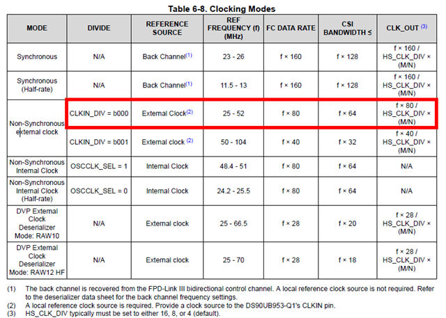
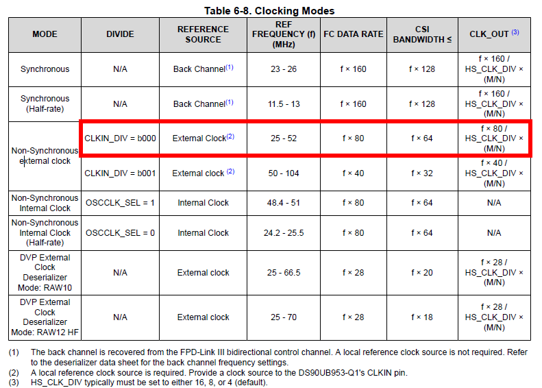
    Note that in asynchronous clocking mode, the forward channel data rate is dependent on the frequency of the external oscillator connected to the 953. If a 27MHz oscillator is used, the forward channel rate is 2.16Gbps and the max CSI bandwidth is 1.728Gbps. If the max bandwidth needed is 330Mbps/lane * 4 lanes = 1.32Gbps, then 27MHz oscillator is sufficient.

    Here is a bring up script which can be used to configure 960 and 953 in your setup. This script can be used with TSER953 + TDES960 or DS90UB953 + DS90UB960.

    """
      Copyright 2025 Texas Instruments Incorporated. All rights reserved.
    
      IMPORTANT: Your use of this Software is limited to those specific rights
      granted under the terms of a software license agreement between the user who
      downloaded the software, his/her employer (which must be your employer) and
      Texas Instruments Incorporated (the "License"). You may not use this Software
      unless you agree to abide by the terms of the License. The License limits your
      use, and you acknowledge, that the Software may not be modified, copied or
      distributed unless embedded on a Texas Instruments microcontroller which is
      integrated into your product. Other than for the foregoing purpose, you may
      not use, reproduce, copy, prepare derivative works of, modify, distribute,
      perform, display or sell this Software and/or its documentation for any
      purpose.
    
      YOU FURTHER ACKNOWLEDGE AND AGREE THAT THE SOFTWARE AND DOCUMENTATION ARE
      PROVIDED AS IS WITHOUT WARRANTY OF ANY KIND, EITHER EXPRESS OR IMPLIED,
      INCLUDING WITHOUT LIMITATION, ANY WARRANTY OF MERCHANTABILITY, TITLE,
      NON-INFRINGEMENT AND FITNESS FOR A PARTICULAR PURPOSE. IN NO EVENT SHALL TEXAS
      INSTRUMENTS OR ITS LICENSORS BE LIABLE OR OBLIGATED UNDER CONTRACT,
      NEGLIGENCE, STRICT LIABILITY, CONTRIBUTION, BREACH OF WARRANTY, OR OTHER LEGAL
      EQUITABLE THEORY ANY DIRECT OR INDIRECT DAMAGES OR EXPENSES INCLUDING BUT NOT
      LIMITED TO ANY INCIDENTAL, SPECIAL, INDIRECT, PUNITIVE OR CONSEQUENTIAL
      DAMAGES, LOST PROFITS OR LOST DATA, COST OF PROCUREMENT OF SUBSTITUTE GOODS,
      TECHNOLOGY, SERVICES, OR ANY CLAIMS BY THIRD PARTIES (INCLUDING BUT NOT
      LIMITED TO ANY DEFENSE THEREOF), OR OTHER SIMILAR COSTS.
    
      Should you have any questions regarding your right to use this Software,
      contact Texas Instruments Incorporated at www.TI.com.
    """
    # Fill in I2C addresses and aliases
    devAddr = 0x60 # 960 deserializer 8-bit I2C address
    serAddr = [0x30,0x30,0x30,0x30] # 953 serializer 8-bit I2C addresses connected to 960 RX port0, port1, port2, port3
    serAlias = [0x1A,0x2A,0x3A,0x4A] # 8-bit I2C aliases to read/write serializers connected to 960 RX port0, port1, port2, port3
    imgAddr = [0x32,0x32,0x32,0x32] # imager 8-bit I2C addresses connected to 960 RX port0, port1, port2, port3
    imgAlias = [0x1C,0x2C,0x3C,0x4C] # 8-bit I2C aliases to read/write imagers connected to 960 RX port0, port1, port2, port3
    ispAddr = [0x34,0x34,0x34,0x34] # ISP 8-bit I2C addresses connected to 960 RX port0, port1, port2, port3
    ispAlias = [0x1E,0x2E,0x3E,0x4E] # 8-bit I2C aliases to read/write ISPs connected to 960 RX port0, port1, port2, port3
    
    import time
    
    for i in range(0,4):
        if i==0:
            board.WriteI2C(devAddr,0x4C,0x01) # select RX port 0
        elif i==1: 
            board.WriteI2C(devAddr,0x4C,0x12) # select RX port 1
        elif i==2:
            board.WriteI2C(devAddr,0x4C,0x24) # select RX port 2
        elif i==3:
            board.WriteI2C(devAddr,0x4C,0x38) # select RX port 3
    
        # auto ACK setup
        board.WriteI2C(devAddr,0x5B,serAddr[i]+1) # set serializer address with freeze
        board.WriteI2C(devAddr,0x5C,serAlias[i]+1) # set SER alias and auto ACK
        board.WriteI2C(devAddr,0x58,0x7A) # Enable I2C passthrough with auto ACK, BC rate = 10Mbps
    
        # 953 config
        board.WriteI2C(serAlias[i],0x02,0x73) # continuous clock, 4 lanes
        board.WriteI2C(serAlias[i],0xE,0x1E) # disable 935 GPIO0 input and enable output
        board.WriteI2C(serAlias[i],0xD,0x10) # Enable remote Des GPIO0 data on local GPIO0
        board.WriteI2C(serAlias[i],0x03,0x12) # MODE override async external clock
        board.WriteI2C(serAlias[i],0x01,0x01) # soft reset
        time.sleep(0.01)
    
        # I2C address and alias setup
        board.WriteI2C(devAddr,0x58,0x5A) # Disable auto ACK
        board.WriteI2C(devAddr,0x5B,serAddr[i]) # remove freeze
        board.WriteI2C(devAddr,0x5C,serAlias[i]) # disable auto ACK
        board.WriteI2C(devAddr,0x5D,imgAddr[i]) # configure imager address
        board.WriteI2C(devAddr,0x65,imgAlias[i]) # configure imager alias
        board.WriteI2C(devAddr,0x5E,ispAddr[i]) # configure ISP address
        board.WriteI2C(devAddr,0x66,ispAlias[i]) # configure ISP alias
    
        # 960 config
        board.WriteI2C(devAddr,0x6D,0x7C) # FPD3 CSI-2 input mode
        board.WriteI2C(devAddr,0x6E,0x8A) # map Fsync signal to 953 GPIO0 output
        board.WriteI2C(devAddr,0x72,0x00) # map VC-ID to 0
    
        # FrameSync: 25Hz, 10%/90% duty cycle
        board.WriteI2C(devAddr,0x19,0x05) # FS_HIGH_TIME_1
        board.WriteI2C(devAddr,0x1A,0x34) # FS_HIGH_TIME_0
        board.WriteI2C(devAddr,0x1B,0x2E) # FS_LOW_TIME_1
        board.WriteI2C(devAddr,0x1C,0xDF) # FS_LOW_TIME_0
        board.WriteI2C(devAddr,0x18,0x01) # enable internally generated FrameSync
    
        # Clear error/status
        time.sleep(0.1)
        board.ReadI2C(devAddr,0x4D)
        board.ReadI2C(devAddr,0x4E)
        board.ReadI2C(devAddr,0x55)
        board.ReadI2C(devAddr,0x56)
        board.ReadI2C(devAddr,0x7A)
        board.ReadI2C(devAddr,0x7B)
    
    # CSI Output / Forwarding Config
    board.WriteI2C(devAddr,0x1F,0x00) # 1.472 - 1.664Gbps serial rate
    board.WriteI2C(devAddr,0x32,0x01) # select CSI port 0
    board.WriteI2C(devAddr,0x33,0x43) # enable skew cal, 4 lanes, continuous clock, enable CSI output
    board.WriteI2C(devAddr,0x21,0x04) # basic sync forwarding on CSI port 0
    board.WriteI2C(devAddr,0x20,0x00) # forward all RX port to CSI port 0, enable forwarding
    

    Please fill in the correct I2C addresses and aliases at the beginning of the script before using. For setups with no ISP included in the camera module, you can use 0x00 for ISP addresses and aliases.

    Currently the FrameSync signal is mapped to the 953 GPIO0 pin. Let me know if this needs to be changed to a different GPIO pin.

    Best,

    Lucas

  • Hi Zhang,

    One more note I'd like to add.

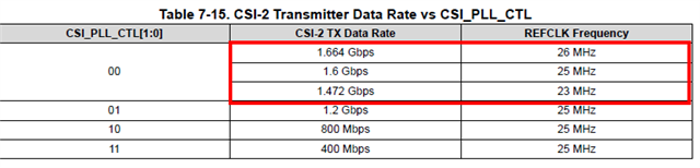
    The 960 CSI output rate is dependent on frequency of the reference clock. The rate is in the range 1.472-1.664Gbps. Skew calibration sequence is enabled in the script I attached.

    Best,

    Lucas

  • Hi Lucas, thank you very much for your configurations, I will try it.

  • Hi Zhang,

    Let me know if you need any support.

    Best,

    Lucas

  • Hi Lucas,

    I'm currently testing with the configuration of the first route.But I can not visit sensor,(8bit slave address, 16 bit register address, 16 bit register value)

    I used " DS90UB960-Q1EVM" and part of the setting you provide (show in the last of this message), I tried to visit below register of sensor,

    So can you help me to connect sensor by DS90UB960-Q1EVM, I want to use this EVM to configure sensor and UB960+UB953 for early development.

    Another question is that I found when configure different address of ser,sensor,isp, you use the same register of UB960(0x5B,0x5C,0x5D,0x65,0x5E,0x66),

    though you select different RX port, will this mutual interference?

    # Fill in I2C addresses and aliases
    devAddr = 0x7A # 960 deserializer 8-bit I2C address
    serAddr = [0x30,0x30,0x30,0x30] # 953 serializer 8-bit I2C addresses connected to 960 RX port0, port1, port2, port3
    serAlias = [0x1A,0x2A,0x3A,0x4A] # 8-bit I2C aliases to read/write serializers connected to 960 RX port0, port1, port2, port3
    imgAddr = [0x30,0x32,0x32,0x32] # imager 8-bit I2C addresses connected to 960 RX port0, port1, port2, port3
    imgAlias = [0x1C,0x2C,0x3C,0x4C] # 8-bit I2C aliases to read/write imagers connected to 960 RX port0, port1, port2, port3
    ispAddr = [0x34,0x34,0x34,0x34] # ISP 8-bit I2C addresses connected to 960 RX port0, port1, port2, port3
    ispAlias = [0x1E,0x2E,0x3E,0x4E] # 8-bit I2C aliases to read/write ISPs connected to 960 RX port0, port1, port2, port3

    import time
    board.WriteI2C(devAddr,0x4C,0x01) # select RX port 0


    # auto ACK setup
    board.WriteI2C(devAddr,0x5B,serAddr[0]+1) # set serializer address with freeze
    board.WriteI2C(devAddr,0x5C,serAlias[0]+1) # set SER alias and auto ACK
    board.WriteI2C(devAddr,0x58,0x7A) # Enable I2C passthrough with auto ACK, BC rate = 10Mbps

    # 953 config
    board.WriteI2C(serAlias[0],0x02,0x73) # continuous clock, 4 lanes
    board.WriteI2C(serAlias[0],0xE,0x1E) # disable 935 GPIO0 input and enable output
    board.WriteI2C(serAlias[0],0xD,0x10) # Enable remote Des GPIO0 data on local GPIO0
    board.WriteI2C(serAlias[0],0x03,0x12) # MODE override async external clock
    board.WriteI2C(serAlias[0],0x01,0x01) # soft reset
    time.sleep(0.01)

    # I2C address and alias setup
    board.WriteI2C(devAddr,0x58,0x5A) # Disable auto ACK
    board.WriteI2C(devAddr,0x5B,serAddr[0]) # remove freeze
    board.WriteI2C(devAddr,0x5C,serAlias[0]) # disable auto ACK

  • Hi Zhang,

    In order to communicate with the imager remotely across the link, it is necessary to configure the imager address and alias in 960 registers 0x5D-0x6C. I see that you removed these registers in your modified script, so it won't be possible to to communicate with the imager. Please add the following lines to your modified script.

    board.WriteI2C(devAddr,0x5D,imgAddr[0]) # configure imager address
    board.WriteI2C(devAddr,0x65,imgAlias[0]) # configure imager alias

    Additionally, please use the imager alias 0x1C as the I2C target address. The 960 will map I2C transactions sent to 0x1C to the correct imager with address 0x30. The purpose of using aliases is to allow remote communication with several serializers, imagers, and other devices which may have the same address.

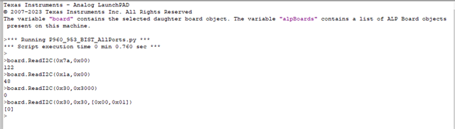
    To read 16-bit register 0x3000 from the imager with ALP, please use the following command.

    board.ReadI2C(0x1C, 0x30, [0x00, 0x02])

    Another question is that I found when configure different address of ser,sensor,isp, you use the same register of UB960(0x5B,0x5C,0x5D,0x65,0x5E,0x66),

    though you select different RX port, will this mutual interference?

    960 registers 0x46-0x7F and 0xD0-0xDF are part of the RX port register page. There are unique copies of these registers for each of the 4 RX ports. Register 0x4C is used to select the correct RX port for register reads/writes. The script I shared with you correctly selects the correct RX port register page with 0x4C before programming registers 0x58-0x66 so there is no concern of overwriting these registers.

    Best,
    Lucas

  • Hi Lucas,

    I want to clarify a question mentioned before:

    Is an external oscillator used in camera modules?
    -------->Yes, it's 27MHz. (what I mean is 27MHz for sensor use, but UB953 use 50MHz external clock)

    So should we update the configuration because of this?

    I encountered a problem that I can not measured MIPI signal output by sensor, but can not measured MIPI signal output by CSI0, can you help me with this?And can you provide some more method for debug with UB960 & UB953? 

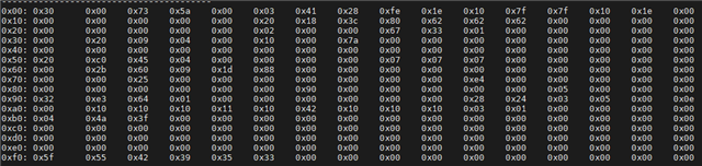
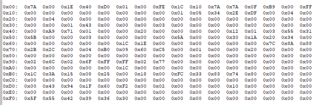
    I now run only 1 module and the MIPI datarate is about 310Mbps/lane, Below is the register I dumped:

    UB953:

    UB960:

    Another problem:

    I can visit sensor with ALP now, also I can visit sensor and UB953 from I2C on CSI0, but can not visit UB960(8bit 0x7A) by CSI0, why is it?

  • Hi Zhang,

    Thank you for the clarification regarding external oscillator. If 50MHz is used with 953, then the forward channel rate is 4Gbps and the max CSI bandwidth is 3.2Gbps. No change is needed to the configuration.

    Thank you for sharing register dumps. I reviewed and see the following.

    • No errors indicated at the 953.
    • 960 register 0x4e indicates LINE_LEN_CHG, BUFFER_ERROR, LINE_CNT_CHG. It's possible these errors occurred during initialization and weren't cleared. It's expected that some errors will be flagged during initialization.
    • Registers 0x73-0x76 indicate 1200 bytes/line, 2400 lines/frame were received by the 960 RX port.
    • Registers 0x90-0x97 indicate several errored frames and lines were detected at the CSI port. It's possible this is because synchronized forwarding is enabled while only one camera module is connected.
    • Register 0x35 indicates the CSI port is not synced and not actively delivering valid video data. This explains why you do not see a video signal on the CSI port output.

    I made a few modifications to the script to handle one camera module only and disable synchronized forwarding. Please try using this script and check if the issue is resolved.

    """
      Copyright 2025 Texas Instruments Incorporated. All rights reserved.
    
      IMPORTANT: Your use of this Software is limited to those specific rights
      granted under the terms of a software license agreement between the user who
      downloaded the software, his/her employer (which must be your employer) and
      Texas Instruments Incorporated (the "License"). You may not use this Software
      unless you agree to abide by the terms of the License. The License limits your
      use, and you acknowledge, that the Software may not be modified, copied or
      distributed unless embedded on a Texas Instruments microcontroller which is
      integrated into your product. Other than for the foregoing purpose, you may
      not use, reproduce, copy, prepare derivative works of, modify, distribute,
      perform, display or sell this Software and/or its documentation for any
      purpose.
    
      YOU FURTHER ACKNOWLEDGE AND AGREE THAT THE SOFTWARE AND DOCUMENTATION ARE
      PROVIDED AS IS WITHOUT WARRANTY OF ANY KIND, EITHER EXPRESS OR IMPLIED,
      INCLUDING WITHOUT LIMITATION, ANY WARRANTY OF MERCHANTABILITY, TITLE,
      NON-INFRINGEMENT AND FITNESS FOR A PARTICULAR PURPOSE. IN NO EVENT SHALL TEXAS
      INSTRUMENTS OR ITS LICENSORS BE LIABLE OR OBLIGATED UNDER CONTRACT,
      NEGLIGENCE, STRICT LIABILITY, CONTRIBUTION, BREACH OF WARRANTY, OR OTHER LEGAL
      EQUITABLE THEORY ANY DIRECT OR INDIRECT DAMAGES OR EXPENSES INCLUDING BUT NOT
      LIMITED TO ANY INCIDENTAL, SPECIAL, INDIRECT, PUNITIVE OR CONSEQUENTIAL
      DAMAGES, LOST PROFITS OR LOST DATA, COST OF PROCUREMENT OF SUBSTITUTE GOODS,
      TECHNOLOGY, SERVICES, OR ANY CLAIMS BY THIRD PARTIES (INCLUDING BUT NOT
      LIMITED TO ANY DEFENSE THEREOF), OR OTHER SIMILAR COSTS.
    
      Should you have any questions regarding your right to use this Software,
      contact Texas Instruments Incorporated at www.TI.com.
    """
    # Fill in I2C addresses and aliases
    devAddr = 0x60 # 960 deserializer 8-bit I2C address
    serAddr = 0x30 # 953 serializer 8-bit I2C address connected to 960 RX port 0
    serAlias = 0x1A # 8-bit I2C alias to read/write serializer connected to 960 RX port0
    imgAddr = 0x30 # imager 8-bit I2C address connected to 960 RX port0
    imgAlias = 0x1C # 8-bit I2C alias to read/write imager connected to 960 RX port0
    
    import time
    
    
    board.WriteI2C(devAddr,0x4C,0x01) # select RX port 0
    
    # auto ACK setup
    board.WriteI2C(devAddr,0x5B,serAddr+1) # set serializer address with freeze
    board.WriteI2C(devAddr,0x5C,serAlias+1) # set SER alias and auto ACK
    board.WriteI2C(devAddr,0x58,0x7A) # Enable I2C passthrough with auto ACK, BC rate = 10Mbps
    
    # 953 config
    board.WriteI2C(serAlias,0x02,0x73) # continuous clock, 4 lanes
    board.WriteI2C(serAlias,0xE,0x1E) # disable 935 GPIO0 input and enable output
    board.WriteI2C(serAlias,0xD,0x10) # Enable remote Des GPIO0 data on local GPIO0
    board.WriteI2C(serAlias,0x03,0x12) # MODE override async external clock
    board.WriteI2C(serAlias,0x01,0x01) # soft reset
    time.sleep(0.01)
    
    # I2C address and alias setup
    board.WriteI2C(devAddr,0x58,0x5A) # Disable auto ACK
    board.WriteI2C(devAddr,0x5B,serAddr) # remove freeze
    board.WriteI2C(devAddr,0x5C,serAlias) # disable auto ACK
    board.WriteI2C(devAddr,0x5D,imgAddr) # configure imager address
    board.WriteI2C(devAddr,0x65,imgAlias) # configure imager alias
    
    # 960 config
    board.WriteI2C(devAddr,0x6D,0x7C) # FPD3 CSI-2 input mode
    board.WriteI2C(devAddr,0x6E,0x8A) # map Fsync signal to 953 GPIO0 output
    board.WriteI2C(devAddr,0x72,0x00) # map VC-ID to 0
    
    # FrameSync: 25Hz, 10%/90% duty cycle
    board.WriteI2C(devAddr,0x19,0x05) # FS_HIGH_TIME_1
    board.WriteI2C(devAddr,0x1A,0x34) # FS_HIGH_TIME_0
    board.WriteI2C(devAddr,0x1B,0x2E) # FS_LOW_TIME_1
    board.WriteI2C(devAddr,0x1C,0xDF) # FS_LOW_TIME_0
    board.WriteI2C(devAddr,0x18,0x01) # enable internally generated FrameSync
    
    # Clear error/status
    time.sleep(0.1)
    board.ReadI2C(devAddr,0x4D)
    board.ReadI2C(devAddr,0x4E)
    board.ReadI2C(devAddr,0x55)
    board.ReadI2C(devAddr,0x56)
    board.ReadI2C(devAddr,0x7A)
    board.ReadI2C(devAddr,0x7B)
    
    # CSI Output / Forwarding Config
    board.WriteI2C(devAddr,0x1F,0x00) # 1.472 - 1.664Gbps serial rate
    board.WriteI2C(devAddr,0x32,0x01) # select CSI port 0
    board.WriteI2C(devAddr,0x33,0x43) # enable skew cal, 4 lanes, continuous clock, enable CSI output
    board.WriteI2C(devAddr,0x21,0x03) # round robin forwarding on CSI port 0
    board.WriteI2C(devAddr,0x20,0xE0) # forward RX port 0 to CSI port 0
    

    After the script completes, can you repeatedly read the following error/status registers with a 1 second interval? This will help to understand if any errors are occurring in short bursts or continuously. I can help you interpret what the values mean.

    • 960: 0x35, 0x4d, 0x4e, 0x55, 0x56, 0x73-0x76, 0x7a, 0x7b, 0x90-0x97
    • 953: 0x52, 0x55, 0x56, 0x5c-0x64

    I can visit sensor with ALP now, also I can visit sensor and UB953 from I2C on CSI0, but can not visit UB960(8bit 0x7A) by CSI0, why is it?

    Just to confirm, you cannot access 960 registers with Orin, although you can access 953 and sensor registers via Orin connected to 960? Is there possibly bus contention with the USB2ANY accessing the 960 at the same time? Or is it possible that 7-bit/8-bit address conversion is incorrect?

    Best,

    Lucas

  • Hi Lucas,

    Thank you very much for your new configuration!

    I can now visit 960 by CSI0 and measure MIPI signal output by CSI0, but I can not analyze the signal by our Jetson platform.

    I saw that we now use CSI_CTL register for Skew, and it only enable initial Skew. But on our platform, it needs to enable both initial Skew and periodic Skew.

    So is it means than we should use CSI1 instead of CSI0, because I saw than periodic Skew can only be enabled on CSI_CTL2.

    If it is, can you provide new configuration for use CSI1? Include visit 960+953 and sensor by CSI1.

    I have another question that I would like to ask you.

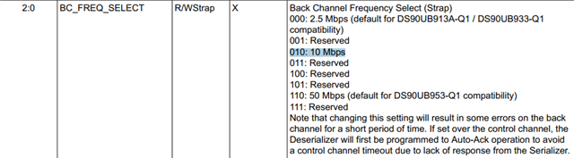
    That  BCC_CONFIG Register(0x58), bit0-2 you choose 10Mbps, what it means? Why we not use 50 Mbps (default for DS90UB953-Q1 compatibility)?

    In addition, we will have the National Day holiday from October 1st to 8th. I will continue to work after the 9th and will contact you then.

    Thank you!

    Qingyu Zhang

  • Hi Zhang,

    Periodic skew calibration can be enabled for both CSI output ports 0 and 1. It is dependent on which CSI port register page is selected in register 0x32. I modified both 1 camera and 4 camera scripts to enable periodic skew calibration on CSI port 0.

    """
      Copyright 2025 Texas Instruments Incorporated. All rights reserved.
    
      IMPORTANT: Your use of this Software is limited to those specific rights
      granted under the terms of a software license agreement between the user who
      downloaded the software, his/her employer (which must be your employer) and
      Texas Instruments Incorporated (the "License"). You may not use this Software
      unless you agree to abide by the terms of the License. The License limits your
      use, and you acknowledge, that the Software may not be modified, copied or
      distributed unless embedded on a Texas Instruments microcontroller which is
      integrated into your product. Other than for the foregoing purpose, you may
      not use, reproduce, copy, prepare derivative works of, modify, distribute,
      perform, display or sell this Software and/or its documentation for any
      purpose.
    
      YOU FURTHER ACKNOWLEDGE AND AGREE THAT THE SOFTWARE AND DOCUMENTATION ARE
      PROVIDED AS IS WITHOUT WARRANTY OF ANY KIND, EITHER EXPRESS OR IMPLIED,
      INCLUDING WITHOUT LIMITATION, ANY WARRANTY OF MERCHANTABILITY, TITLE,
      NON-INFRINGEMENT AND FITNESS FOR A PARTICULAR PURPOSE. IN NO EVENT SHALL TEXAS
      INSTRUMENTS OR ITS LICENSORS BE LIABLE OR OBLIGATED UNDER CONTRACT,
      NEGLIGENCE, STRICT LIABILITY, CONTRIBUTION, BREACH OF WARRANTY, OR OTHER LEGAL
      EQUITABLE THEORY ANY DIRECT OR INDIRECT DAMAGES OR EXPENSES INCLUDING BUT NOT
      LIMITED TO ANY INCIDENTAL, SPECIAL, INDIRECT, PUNITIVE OR CONSEQUENTIAL
      DAMAGES, LOST PROFITS OR LOST DATA, COST OF PROCUREMENT OF SUBSTITUTE GOODS,
      TECHNOLOGY, SERVICES, OR ANY CLAIMS BY THIRD PARTIES (INCLUDING BUT NOT
      LIMITED TO ANY DEFENSE THEREOF), OR OTHER SIMILAR COSTS.
    
      Should you have any questions regarding your right to use this Software,
      contact Texas Instruments Incorporated at www.TI.com.
    """
    # Fill in I2C addresses and aliases
    devAddr = 0x60 # 960 deserializer 8-bit I2C address
    serAddr = 0x30 # 953 serializer 8-bit I2C address connected to 960 RX port 0
    serAlias = 0x1A # 8-bit I2C alias to read/write serializer connected to 960 RX port0
    imgAddr = 0x30 # imager 8-bit I2C address connected to 960 RX port0
    imgAlias = 0x1C # 8-bit I2C alias to read/write imager connected to 960 RX port0
    
    import time
    
    
    board.WriteI2C(devAddr,0x4C,0x01) # select RX port 0
    
    # auto ACK setup
    board.WriteI2C(devAddr,0x5B,serAddr+1) # set serializer address with freeze
    board.WriteI2C(devAddr,0x5C,serAlias+1) # set SER alias and auto ACK
    board.WriteI2C(devAddr,0x58,0x7A) # Enable I2C passthrough with auto ACK, BC rate = 10Mbps
    
    # 953 config
    board.WriteI2C(serAlias,0x02,0x73) # continuous clock, 4 lanes
    board.WriteI2C(serAlias,0xE,0x1E) # disable 935 GPIO0 input and enable output
    board.WriteI2C(serAlias,0xD,0x10) # Enable remote Des GPIO0 data on local GPIO0
    board.WriteI2C(serAlias,0x03,0x12) # MODE override async external clock
    board.WriteI2C(serAlias,0x01,0x01) # soft reset
    time.sleep(0.01)
    
    # I2C address and alias setup
    board.WriteI2C(devAddr,0x58,0x5A) # Disable auto ACK
    board.WriteI2C(devAddr,0x5B,serAddr) # remove freeze
    board.WriteI2C(devAddr,0x5C,serAlias) # disable auto ACK
    board.WriteI2C(devAddr,0x5D,imgAddr) # configure imager address
    board.WriteI2C(devAddr,0x65,imgAlias) # configure imager alias
    
    # 960 config
    board.WriteI2C(devAddr,0x6D,0x7C) # FPD3 CSI-2 input mode
    board.WriteI2C(devAddr,0x6E,0x8A) # map Fsync signal to 953 GPIO0 output
    board.WriteI2C(devAddr,0x72,0x00) # map VC-ID to 0
    
    # FrameSync: 25Hz, 10%/90% duty cycle
    board.WriteI2C(devAddr,0x19,0x05) # FS_HIGH_TIME_1
    board.WriteI2C(devAddr,0x1A,0x34) # FS_HIGH_TIME_0
    board.WriteI2C(devAddr,0x1B,0x2E) # FS_LOW_TIME_1
    board.WriteI2C(devAddr,0x1C,0xDF) # FS_LOW_TIME_0
    board.WriteI2C(devAddr,0x18,0x01) # enable internally generated FrameSync
    
    # Clear error/status
    time.sleep(0.1)
    board.ReadI2C(devAddr,0x4D)
    board.ReadI2C(devAddr,0x4E)
    board.ReadI2C(devAddr,0x55)
    board.ReadI2C(devAddr,0x56)
    board.ReadI2C(devAddr,0x7A)
    board.ReadI2C(devAddr,0x7B)
    
    # CSI Output / Forwarding Config
    board.WriteI2C(devAddr,0x1F,0x00) # 1.472 - 1.664Gbps serial rate
    board.WriteI2C(devAddr,0x32,0x01) # select CSI port 0
    board.WriteI2C(devAddr,0x34,0x01) # enable periodic skew cal
    board.WriteI2C(devAddr,0x33,0x43) # enable skew cal, 4 lanes, continuous clock, enable CSI output
    board.WriteI2C(devAddr,0x21,0x03) # round robin forwarding on CSI port 0
    board.WriteI2C(devAddr,0x20,0xE0) # forward RX port 0 to CSI port 0
    

    """
      Copyright 2025 Texas Instruments Incorporated. All rights reserved.
    
      IMPORTANT: Your use of this Software is limited to those specific rights
      granted under the terms of a software license agreement between the user who
      downloaded the software, his/her employer (which must be your employer) and
      Texas Instruments Incorporated (the "License"). You may not use this Software
      unless you agree to abide by the terms of the License. The License limits your
      use, and you acknowledge, that the Software may not be modified, copied or
      distributed unless embedded on a Texas Instruments microcontroller which is
      integrated into your product. Other than for the foregoing purpose, you may
      not use, reproduce, copy, prepare derivative works of, modify, distribute,
      perform, display or sell this Software and/or its documentation for any
      purpose.
    
      YOU FURTHER ACKNOWLEDGE AND AGREE THAT THE SOFTWARE AND DOCUMENTATION ARE
      PROVIDED AS IS WITHOUT WARRANTY OF ANY KIND, EITHER EXPRESS OR IMPLIED,
      INCLUDING WITHOUT LIMITATION, ANY WARRANTY OF MERCHANTABILITY, TITLE,
      NON-INFRINGEMENT AND FITNESS FOR A PARTICULAR PURPOSE. IN NO EVENT SHALL TEXAS
      INSTRUMENTS OR ITS LICENSORS BE LIABLE OR OBLIGATED UNDER CONTRACT,
      NEGLIGENCE, STRICT LIABILITY, CONTRIBUTION, BREACH OF WARRANTY, OR OTHER LEGAL
      EQUITABLE THEORY ANY DIRECT OR INDIRECT DAMAGES OR EXPENSES INCLUDING BUT NOT
      LIMITED TO ANY INCIDENTAL, SPECIAL, INDIRECT, PUNITIVE OR CONSEQUENTIAL
      DAMAGES, LOST PROFITS OR LOST DATA, COST OF PROCUREMENT OF SUBSTITUTE GOODS,
      TECHNOLOGY, SERVICES, OR ANY CLAIMS BY THIRD PARTIES (INCLUDING BUT NOT
      LIMITED TO ANY DEFENSE THEREOF), OR OTHER SIMILAR COSTS.
    
      Should you have any questions regarding your right to use this Software,
      contact Texas Instruments Incorporated at www.TI.com.
    """
    # Fill in I2C addresses and aliases
    devAddr = 0x60 # 960 deserializer 8-bit I2C address
    serAddr = [0x30,0x30,0x30,0x30] # 953 serializer 8-bit I2C addresses connected to 960 RX port0, port1, port2, port3
    serAlias = [0x1A,0x2A,0x3A,0x4A] # 8-bit I2C aliases to read/write serializers connected to 960 RX port0, port1, port2, port3
    imgAddr = [0x32,0x32,0x32,0x32] # imager 8-bit I2C addresses connected to 960 RX port0, port1, port2, port3
    imgAlias = [0x1C,0x2C,0x3C,0x4C] # 8-bit I2C aliases to read/write imagers connected to 960 RX port0, port1, port2, port3
    ispAddr = [0x34,0x34,0x34,0x34] # ISP 8-bit I2C addresses connected to 960 RX port0, port1, port2, port3
    ispAlias = [0x1E,0x2E,0x3E,0x4E] # 8-bit I2C aliases to read/write ISPs connected to 960 RX port0, port1, port2, port3
    
    import time
    
    for i in range(0,4):
        if i==0:
            board.WriteI2C(devAddr,0x4C,0x01) # select RX port 0
        elif i==1: 
            board.WriteI2C(devAddr,0x4C,0x12) # select RX port 1
        elif i==2:
            board.WriteI2C(devAddr,0x4C,0x24) # select RX port 2
        elif i==3:
            board.WriteI2C(devAddr,0x4C,0x38) # select RX port 3
    
        # auto ACK setup
        board.WriteI2C(devAddr,0x5B,serAddr[i]+1) # set serializer address with freeze
        board.WriteI2C(devAddr,0x5C,serAlias[i]+1) # set SER alias and auto ACK
        board.WriteI2C(devAddr,0x58,0x7A) # Enable I2C passthrough with auto ACK, BC rate = 10Mbps
    
        # 953 config
        board.WriteI2C(serAlias[i],0x02,0x73) # continuous clock, 4 lanes
        board.WriteI2C(serAlias[i],0xE,0x1E) # disable 935 GPIO0 input and enable output
        board.WriteI2C(serAlias[i],0xD,0x10) # Enable remote Des GPIO0 data on local GPIO0
        board.WriteI2C(serAlias[i],0x03,0x12) # MODE override async external clock
        board.WriteI2C(serAlias[i],0x01,0x01) # soft reset
        time.sleep(0.01)
    
        # I2C address and alias setup
        board.WriteI2C(devAddr,0x58,0x5A) # Disable auto ACK
        board.WriteI2C(devAddr,0x5B,serAddr[i]) # remove freeze
        board.WriteI2C(devAddr,0x5C,serAlias[i]) # disable auto ACK
        board.WriteI2C(devAddr,0x5D,imgAddr[i]) # configure imager address
        board.WriteI2C(devAddr,0x65,imgAlias[i]) # configure imager alias
        board.WriteI2C(devAddr,0x5E,ispAddr[i]) # configure ISP address
        board.WriteI2C(devAddr,0x66,ispAlias[i]) # configure ISP alias
    
        # 960 config
        board.WriteI2C(devAddr,0x6D,0x7C) # FPD3 CSI-2 input mode
        board.WriteI2C(devAddr,0x6E,0x8A) # map Fsync signal to 953 GPIO0 output
        board.WriteI2C(devAddr,0x72,0x00) # map VC-ID to 0
    
        # FrameSync: 25Hz, 10%/90% duty cycle
        board.WriteI2C(devAddr,0x19,0x05) # FS_HIGH_TIME_1
        board.WriteI2C(devAddr,0x1A,0x34) # FS_HIGH_TIME_0
        board.WriteI2C(devAddr,0x1B,0x2E) # FS_LOW_TIME_1
        board.WriteI2C(devAddr,0x1C,0xDF) # FS_LOW_TIME_0
        board.WriteI2C(devAddr,0x18,0x01) # enable internally generated FrameSync
    
        # Clear error/status
        time.sleep(0.1)
        board.ReadI2C(devAddr,0x4D)
        board.ReadI2C(devAddr,0x4E)
        board.ReadI2C(devAddr,0x55)
        board.ReadI2C(devAddr,0x56)
        board.ReadI2C(devAddr,0x7A)
        board.ReadI2C(devAddr,0x7B)
    
    # CSI Output / Forwarding Config
    board.WriteI2C(devAddr,0x1F,0x00) # 1.472 - 1.664Gbps serial rate
    board.WriteI2C(devAddr,0x32,0x01) # select CSI port 0
    board.WriteI2C(devAddr,0x34,0x01) # enable periodic skew cal
    board.WriteI2C(devAddr,0x33,0x43) # enable skew cal, 4 lanes, continuous clock, enable CSI output
    board.WriteI2C(devAddr,0x21,0x04) # basic sync forwarding on CSI port 0
    board.WriteI2C(devAddr,0x20,0x00) # forward all RX port to CSI port 0, enable forwarding
    

    50Mbps back channel frequency is the default setting for synchronous clocking mode, where the serializer reference clock is sent across the back channel from the deserializer. Since you are using non-synchronous clocking mode, where the serializer reference clock is provided by an external oscillator, I programmed 10Mbps back channel frequency. This is the default setting for non-synchronous clocking mode.

    I hope you have a good holiday break!

    Best,

    Lucas

  • Hi Lucas,

    Thanks for the information, and I now can get 4 route video(raw).

    I am working on yuv camera with ISP now.

    Below is the configuration I used:

    # Fill in I2C addresses and aliases
    devAddr = 0x7A # 960 deserializer 8-bit I2C address
    serAddr = [0x30,0x30,0x30,0x30] # 953 serializer 8-bit I2C addresses connected to 960 RX port0, port1, port2, port3
    serAlias = [0x1A,0x2A,0x3A,0x4A] # 8-bit I2C aliases to read/write serializers connected to 960 RX port0, port1, port2, port3
    imgAddr = [0x20,0x20,0x20,0x20] # imager 8-bit I2C addresses connected to 960 RX port0, port1, port2, port3
    imgAlias = [0x20,0x22,0x24,0x26] # 8-bit I2C aliases to read/write imagers connected to 960 RX port0, port1, port2, port3
    ispAddr = [0x78,0x78,0x78,0x78] # ISP 8-bit I2C addresses connected to 960 RX port0, port1, port2, port3
    ispAlias = [0x78,0x2E,0x3E,0x4E] # 8-bit I2C aliases to read/write ISPs connected to 960 RX port0, port1, port2, port3

    import time

    for i in range(0,4):
    if i==0:
    board.WriteI2C(devAddr,0x4C,0x01) # select RX port 0
    elif i==1:
    board.WriteI2C(devAddr,0x4C,0x12) # select RX port 1
    elif i==2:
    board.WriteI2C(devAddr,0x4C,0x24) # select RX port 2
    elif i==3:
    board.WriteI2C(devAddr,0x4C,0x38) # select RX port 3

    # auto ACK setup
    board.WriteI2C(devAddr,0x5B,serAddr[i]+1) # set serializer address with freeze
    board.WriteI2C(devAddr,0x5C,serAlias[i]+1) # set SER alias and auto ACK
    board.WriteI2C(devAddr,0x58,0x7A) # Enable I2C passthrough with auto ACK, BC rate = 10Mbps

    # 953 config
    board.WriteI2C(serAlias[i],0x02,0x73) # continuous clock, 4 lanes
    board.WriteI2C(serAlias[i],0xE,0x1E) # disable 935 GPIO0 input and enable output
    board.WriteI2C(serAlias[i],0xD,0x10) # Enable remote Des GPIO0 data on local GPIO0
    board.WriteI2C(serAlias[i],0x03,0x12) # MODE override async external clock
    board.WriteI2C(serAlias[i],0x01,0x01) # soft reset
    time.sleep(0.01)

    # I2C address and alias setup
    board.WriteI2C(devAddr,0x58,0x5A) # Disable auto ACK
    board.WriteI2C(devAddr,0x5B,serAddr[i]) # remove freeze
    board.WriteI2C(devAddr,0x5C,serAlias[i]) # disable auto ACK
    board.WriteI2C(devAddr,0x5D,imgAddr[i]) # configure imager address
    board.WriteI2C(devAddr,0x65,imgAlias[i]) # configure imager alias
    board.WriteI2C(devAddr,0x5E,ispAddr[i]) # configure ISP address
    board.WriteI2C(devAddr,0x66,ispAlias[i]) # configure ISP alias

    # 960 config
    board.WriteI2C(devAddr,0x6D,0x7C) # FPD3 CSI-2 input mode
    board.WriteI2C(devAddr,0x6E,0x8A) # map Fsync signal to 953 GPIO0 output
    #board.WriteI2C(devAddr,0x72,0x00) # map VC-ID to 0
    board.WriteI2C(devAddr,0x72,i) # map VC-ID to i

    # FrameSync: 25Hz, 10%/90% duty cycle
    board.WriteI2C(devAddr,0x19,0x05) # FS_HIGH_TIME_1
    board.WriteI2C(devAddr,0x1A,0x34) # FS_HIGH_TIME_0
    board.WriteI2C(devAddr,0x1B,0x2E) # FS_LOW_TIME_1
    board.WriteI2C(devAddr,0x1C,0xDF) # FS_LOW_TIME_0
    board.WriteI2C(devAddr,0x18,0x01) # enable internally generated FrameSync

    # Clear error/status
    time.sleep(0.1)
    board.ReadI2C(devAddr,0x4D)
    board.ReadI2C(devAddr,0x4E)
    board.ReadI2C(devAddr,0x55)
    board.ReadI2C(devAddr,0x56)
    board.ReadI2C(devAddr,0x7A)
    board.ReadI2C(devAddr,0x7B)

    # CSI Output / Forwarding Config
    board.WriteI2C(devAddr,0x1F,0x00) # 1.472 - 1.664Gbps serial rate
    board.WriteI2C(devAddr,0x32,0x01) # select CSI port 0
    #board.WriteI2C(devAddr,0x34,0x01)
    board.WriteI2C(devAddr,0x34,0x73) # enable skew
    board.WriteI2C(devAddr,0x33,0x43) # enable skew cal, 4 lanes, continuous clock, enable CSI output
    #board.WriteI2C(devAddr,0x21,0x04) # basic sync forwarding on CSI port 0
    #board.WriteI2C(devAddr,0x20,0x00) # forward all RX port to CSI port 0, enable forwarding
    board.WriteI2C(devAddr,0x21,0x03) # basic sync forwarding on CSI port 0
    board.WriteI2C(devAddr,0x20,0x00) # forward all RX port to CSI port 0, enable forwarding

  • Hi Zhang,

    I'm glad to hear your 4 camera RAW10 setup is working. For YUV setup, I see you made the following changes to the script I shared.

    board.WriteI2C(devAddr,0x72,i) # map VC-ID to i

    • Note that this configuration only remaps the VC-ID if the incoming video stream has VC-ID 0. If the incoming video stream has any other VC-ID, it will not be remapped.

    board.WriteI2C(devAddr,0x34,0x73) # enable skew

    • This setting attempts to overwrite a reserved read-only field (bit 6). Periodic calibration sequence is increased to 2^15 bits. Both single and periodic skew calibration are enabled.
    • I'd like to check why bit 6 is being asserted and why both single and periodic skew calibration are enabled? Typically I'd recommend setting 0x34=0x31 for periodic skew calibration with longer sequence length.

    board.WriteI2C(devAddr,0x21,0x03) # basic sync forwarding on CSI port 0

    • This setting enables round robin forwarding instead of basic synchronized forwarding. This means packets are forwarded to the CSI output as soon as they are available and no attempt is made to synchronize the video traffic.

    Best,

    Lucas

  • Hi Lucas,

    I can get 4 route YUV success now, thank you very much!

    I want to ask that if I dont Clear error/status, will it affect UB960-UB953 function?

    Below is the configuration I used for 4 YUV

    """
    Copyright 2025 Texas Instruments Incorporated. All rights reserved.

    IMPORTANT: Your use of this Software is limited to those specific rights
    granted under the terms of a software license agreement between the user who
    downloaded the software, his/her employer (which must be your employer) and
    Texas Instruments Incorporated (the "License"). You may not use this Software
    unless you agree to abide by the terms of the License. The License limits your
    use, and you acknowledge, that the Software may not be modified, copied or
    distributed unless embedded on a Texas Instruments microcontroller which is
    integrated into your product. Other than for the foregoing purpose, you may
    not use, reproduce, copy, prepare derivative works of, modify, distribute,
    perform, display or sell this Software and/or its documentation for any
    purpose.

    YOU FURTHER ACKNOWLEDGE AND AGREE THAT THE SOFTWARE AND DOCUMENTATION ARE
    PROVIDED AS IS WITHOUT WARRANTY OF ANY KIND, EITHER EXPRESS OR IMPLIED,
    INCLUDING WITHOUT LIMITATION, ANY WARRANTY OF MERCHANTABILITY, TITLE,
    NON-INFRINGEMENT AND FITNESS FOR A PARTICULAR PURPOSE. IN NO EVENT SHALL TEXAS
    INSTRUMENTS OR ITS LICENSORS BE LIABLE OR OBLIGATED UNDER CONTRACT,
    NEGLIGENCE, STRICT LIABILITY, CONTRIBUTION, BREACH OF WARRANTY, OR OTHER LEGAL
    EQUITABLE THEORY ANY DIRECT OR INDIRECT DAMAGES OR EXPENSES INCLUDING BUT NOT
    LIMITED TO ANY INCIDENTAL, SPECIAL, INDIRECT, PUNITIVE OR CONSEQUENTIAL
    DAMAGES, LOST PROFITS OR LOST DATA, COST OF PROCUREMENT OF SUBSTITUTE GOODS,
    TECHNOLOGY, SERVICES, OR ANY CLAIMS BY THIRD PARTIES (INCLUDING BUT NOT
    LIMITED TO ANY DEFENSE THEREOF), OR OTHER SIMILAR COSTS.

    Should you have any questions regarding your right to use this Software,
    contact Texas Instruments Incorporated at www.TI.com.
    """
    # Fill in I2C addresses and aliases
    devAddr = 0x7A # 960 deserializer 8-bit I2C address
    serAddr = [0x30,0x30,0x30,0x30] # 953 serializer 8-bit I2C addresses connected to 960 RX port0, port1, port2, port3
    serAlias = [0x1A,0x2A,0x3A,0x4A] # 8-bit I2C aliases to read/write serializers connected to 960 RX port0, port1, port2, port3
    imgAddr = [0x20,0x20,0x20,0x20] # imager 8-bit I2C addresses connected to 960 RX port0, port1, port2, port3
    imgAlias = [0x20,0x22,0x24,0x26] # 8-bit I2C aliases to read/write imagers connected to 960 RX port0, port1, port2, port3
    ispAddr = [0x78,0x78,0x78,0x78] # ISP 8-bit I2C addresses connected to 960 RX port0, port1, port2, port3
    ispAlias = [0x40,0x42,0x44,0x46] # 8-bit I2C aliases to read/write ISPs connected to 960 RX port0, port1, port2, port3

    import time

    for i in range(0,4):
    if i==0:
    board.WriteI2C(devAddr,0x4C,0x01) # select RX port 0
    elif i==1:
    board.WriteI2C(devAddr,0x4C,0x12) # select RX port 1
    elif i==2:
    board.WriteI2C(devAddr,0x4C,0x24) # select RX port 2
    elif i==3:
    board.WriteI2C(devAddr,0x4C,0x38) # select RX port 3

    # auto ACK setup
    board.WriteI2C(devAddr,0x5B,serAddr[i]+1) # set serializer address with freeze
    board.WriteI2C(devAddr,0x5C,serAlias[i]+1) # set SER alias and auto ACK
    board.WriteI2C(devAddr,0x58,0x7A) # Enable I2C passthrough with auto ACK, BC rate = 10Mbps

    # 953 config
    board.WriteI2C(serAlias[i],0x02,0x73) # continuous clock, 4 lanes
    board.WriteI2C(serAlias[i],0xE,0x1E) # disable 935 GPIO0 input and enable output
    board.WriteI2C(serAlias[i],0xD,0x10) # Enable remote Des GPIO0 data on local GPIO0
    board.WriteI2C(serAlias[i],0x03,0x12) # MODE override async external clock
    board.WriteI2C(serAlias[i],0x01,0x01) # soft reset
    time.sleep(0.01)

    # I2C address and alias setup
    board.WriteI2C(devAddr,0x58,0x5A) # Disable auto ACK
    board.WriteI2C(devAddr,0x5B,serAddr[i]) # remove freeze
    board.WriteI2C(devAddr,0x5C,serAlias[i]) # disable auto ACK
    board.WriteI2C(devAddr,0x5D,imgAddr[i]) # configure imager address
    board.WriteI2C(devAddr,0x65,imgAlias[i]) # configure imager alias
    board.WriteI2C(devAddr,0x5E,ispAddr[i]) # configure ISP address
    board.WriteI2C(devAddr,0x66,ispAlias[i]) # configure ISP alias

    # 960 config
    board.WriteI2C(devAddr,0x6D,0x7C) # FPD3 CSI-2 input mode
    board.WriteI2C(devAddr,0x6E,0x8A) # map Fsync signal to 953 GPIO0 output
    #board.WriteI2C(devAddr,0x72,0x00) # map VC-ID to 0
    board.WriteI2C(devAddr,0x72,i) # map VC-ID to i

    # FrameSync: 25Hz, 10%/90% duty cycle
    board.WriteI2C(devAddr,0x19,0x05) # FS_HIGH_TIME_1
    board.WriteI2C(devAddr,0x1A,0x34) # FS_HIGH_TIME_0
    #board.WriteI2C(devAddr,0x1B,0x2E) # FS_LOW_TIME_1 25fps
    #board.WriteI2C(devAddr,0x1C,0xDF) # FS_LOW_TIME_0 25fps
    board.WriteI2C(devAddr,0x1B,0x26) # FS_LOW_TIME_1 30fps
    board.WriteI2C(devAddr,0x1C,0x26) # FS_LOW_TIME_0 30fps
    #board.WriteI2C(devAddr,0x1B,0x7C) # FS_LOW_TIME_1
    #board.WriteI2C(devAddr,0x1C,0xFB) # FS_LOW_TIME_0
    board.WriteI2C(devAddr,0x18,0x01) # enable internally generated FrameSync

    # Clear error/status
    time.sleep(0.1)
    board.ReadI2C(devAddr,0x4D)
    board.ReadI2C(devAddr,0x4E)
    board.ReadI2C(devAddr,0x55)
    board.ReadI2C(devAddr,0x56)
    board.ReadI2C(devAddr,0x7A)
    board.ReadI2C(devAddr,0x7B)

    # CSI Output / Forwarding Config
    board.WriteI2C(devAddr,0x1F,0x00) # 1.472 - 1.664Gbps serial rate
    board.WriteI2C(devAddr,0x32,0x01) # select CSI port 0
    #board.WriteI2C(devAddr,0x34,0x01)
    board.WriteI2C(devAddr,0x34,0x31) # enable skew
    board.WriteI2C(devAddr,0x33,0x43) # enable skew cal, 4 lanes, continuous clock, enable CSI output
    #board.WriteI2C(devAddr,0x21,0x04) # basic sync forwarding on CSI port 0
    #board.WriteI2C(devAddr,0x20,0x00) # forward all RX port to CSI port 0, enable forwarding
    board.WriteI2C(devAddr,0x21,0x03) # basic sync forwarding on CSI port 0
    board.WriteI2C(devAddr,0x20,0x00) # forward all RX port to CSI port 0, enable forwarding

  • Hi Zhang,

    Good to hear 4 cameras YUV setup is working.

    It will not impact operation if you remove register reads to clear error/status. Keep in mind that if you later need to check error/status registers, the first readback needs to be ignored.

    It is expected that several errors may be flagged during initialization which don't indicate any real issue. A register readback is necessary to clear these flags.

    Best,

    Lucas

  • Hi Lucas,

    Thanks for your explanation!

    I have another requirements in terms of synchronization.

    I will use two UB960 to link total 8 cameras, and all these cameras should SYNC.

    So I want to use our Xavier NX to provide trigger signal to GPIO4 of UB960,and output from GPIO0 of Ti953.

    Can you provide the configuration of it, instead of generate FrameSync signal by UB960?

  • Hi Zhang,

    Please use the following script for configuration with external FrameSync.

    """
    Copyright 2025 Texas Instruments Incorporated. All rights reserved.
    
    IMPORTANT: Your use of this Software is limited to those specific rights
    granted under the terms of a software license agreement between the user who
    downloaded the software, his/her employer (which must be your employer) and
    Texas Instruments Incorporated (the "License"). You may not use this Software
    unless you agree to abide by the terms of the License. The License limits your
    use, and you acknowledge, that the Software may not be modified, copied or
    distributed unless embedded on a Texas Instruments microcontroller which is
    integrated into your product. Other than for the foregoing purpose, you may
    not use, reproduce, copy, prepare derivative works of, modify, distribute,
    perform, display or sell this Software and/or its documentation for any
    purpose.
    
    YOU FURTHER ACKNOWLEDGE AND AGREE THAT THE SOFTWARE AND DOCUMENTATION ARE
    PROVIDED AS IS WITHOUT WARRANTY OF ANY KIND, EITHER EXPRESS OR IMPLIED,
    INCLUDING WITHOUT LIMITATION, ANY WARRANTY OF MERCHANTABILITY, TITLE,
    NON-INFRINGEMENT AND FITNESS FOR A PARTICULAR PURPOSE. IN NO EVENT SHALL TEXAS
    INSTRUMENTS OR ITS LICENSORS BE LIABLE OR OBLIGATED UNDER CONTRACT,
    NEGLIGENCE, STRICT LIABILITY, CONTRIBUTION, BREACH OF WARRANTY, OR OTHER LEGAL
    EQUITABLE THEORY ANY DIRECT OR INDIRECT DAMAGES OR EXPENSES INCLUDING BUT NOT
    LIMITED TO ANY INCIDENTAL, SPECIAL, INDIRECT, PUNITIVE OR CONSEQUENTIAL
    DAMAGES, LOST PROFITS OR LOST DATA, COST OF PROCUREMENT OF SUBSTITUTE GOODS,
    TECHNOLOGY, SERVICES, OR ANY CLAIMS BY THIRD PARTIES (INCLUDING BUT NOT
    LIMITED TO ANY DEFENSE THEREOF), OR OTHER SIMILAR COSTS.
    
    Should you have any questions regarding your right to use this Software,
    contact Texas Instruments Incorporated at www.TI.com.
    """
    # Fill in I2C addresses and aliases
    devAddr = 0x7A # 960 deserializer 8-bit I2C address
    serAddr = [0x30,0x30,0x30,0x30] # 953 serializer 8-bit I2C addresses connected to 960 RX port0, port1, port2, port3
    serAlias = [0x1A,0x2A,0x3A,0x4A] # 8-bit I2C aliases to read/write serializers connected to 960 RX port0, port1, port2, port3
    imgAddr = [0x20,0x20,0x20,0x20] # imager 8-bit I2C addresses connected to 960 RX port0, port1, port2, port3
    imgAlias = [0x20,0x22,0x24,0x26] # 8-bit I2C aliases to read/write imagers connected to 960 RX port0, port1, port2, port3
    ispAddr = [0x78,0x78,0x78,0x78] # ISP 8-bit I2C addresses connected to 960 RX port0, port1, port2, port3
    ispAlias = [0x40,0x42,0x44,0x46] # 8-bit I2C aliases to read/write ISPs connected to 960 RX port0, port1, port2, port3
    
    import time
    
    for i in range(0,4):
        if i==0:
            board.WriteI2C(devAddr,0x4C,0x01) # select RX port 0
        elif i==1:
            board.WriteI2C(devAddr,0x4C,0x12) # select RX port 1
        elif i==2:
            board.WriteI2C(devAddr,0x4C,0x24) # select RX port 2
        elif i==3:
            board.WriteI2C(devAddr,0x4C,0x38) # select RX port 3
    
        # auto ACK setup
        board.WriteI2C(devAddr,0x5B,serAddr[i]+1) # set serializer address with freeze
        board.WriteI2C(devAddr,0x5C,serAlias[i]+1) # set SER alias and auto ACK
        board.WriteI2C(devAddr,0x58,0x7A) # Enable I2C passthrough with auto ACK, BC rate = 10Mbps
    
        # 953 config
        board.WriteI2C(serAlias[i],0x02,0x73) # continuous clock, 4 lanes
        board.WriteI2C(serAlias[i],0xE,0x1E) # disable 935 GPIO0 input and enable output
        board.WriteI2C(serAlias[i],0xD,0x10) # Enable remote Des GPIO0 data on local GPIO0
        board.WriteI2C(serAlias[i],0x03,0x12) # MODE override async external clock
        board.WriteI2C(serAlias[i],0x01,0x01) # soft reset
        time.sleep(0.01)
    
        # I2C address and alias setup
        board.WriteI2C(devAddr,0x58,0x5A) # Disable auto ACK
        board.WriteI2C(devAddr,0x5B,serAddr[i]) # remove freeze
        board.WriteI2C(devAddr,0x5C,serAlias[i]) # disable auto ACK
        board.WriteI2C(devAddr,0x5D,imgAddr[i]) # configure imager address
        board.WriteI2C(devAddr,0x65,imgAlias[i]) # configure imager alias
        board.WriteI2C(devAddr,0x5E,ispAddr[i]) # configure ISP address
        board.WriteI2C(devAddr,0x66,ispAlias[i]) # configure ISP alias
    
        # 960 config
        board.WriteI2C(devAddr,0x6D,0x7C) # FPD3 CSI-2 input mode
        board.WriteI2C(devAddr,0x6E,0x8A) # map Fsync signal to 953 GPIO0 output
        #board.WriteI2C(devAddr,0x72,0x00) # map VC-ID to 0
        board.WriteI2C(devAddr,0x72,i) # map VC-ID to i
    
    # FrameSync: 25Hz, 10%/90% duty cycle
    #board.WriteI2C(devAddr,0x19,0x05) # FS_HIGH_TIME_1
    #board.WriteI2C(devAddr,0x1A,0x34) # FS_HIGH_TIME_0
    #board.WriteI2C(devAddr,0x1B,0x2E) # FS_LOW_TIME_1 25fps
    #board.WriteI2C(devAddr,0x1C,0xDF) # FS_LOW_TIME_0 25fps
    #board.WriteI2C(devAddr,0x1B,0x26) # FS_LOW_TIME_1 30fps
    #board.WriteI2C(devAddr,0x1C,0x26) # FS_LOW_TIME_0 30fps
    #board.WriteI2C(devAddr,0x1B,0x7C) # FS_LOW_TIME_1
    #board.WriteI2C(devAddr,0x1C,0xFB) # FS_LOW_TIME_0
    #board.WriteI2C(devAddr,0x18,0x01) # enable internally generated FrameSync
    
    # FrameSync: external from GPIO4 input signal. FS_GEN_ENABLE=0 for external FrameSync mode
    board.WriteI2C(devAddr,0x18,0xC0)
    
    # Clear error/status
    time.sleep(0.1)
    board.ReadI2C(devAddr,0x4D)
    board.ReadI2C(devAddr,0x4E)
    board.ReadI2C(devAddr,0x55)
    board.ReadI2C(devAddr,0x56)
    board.ReadI2C(devAddr,0x7A)
    board.ReadI2C(devAddr,0x7B)
    
    # CSI Output / Forwarding Config
    board.WriteI2C(devAddr,0x1F,0x00) # 1.472 - 1.664Gbps serial rate
    board.WriteI2C(devAddr,0x32,0x01) # select CSI port 0
    #board.WriteI2C(devAddr,0x34,0x01)
    board.WriteI2C(devAddr,0x34,0x31) # enable skew
    board.WriteI2C(devAddr,0x33,0x43) # enable skew cal, 4 lanes, continuous clock, enable CSI output
    #board.WriteI2C(devAddr,0x21,0x04) # basic sync forwarding on CSI port 0
    #board.WriteI2C(devAddr,0x20,0x00) # forward all RX port to CSI port 0, enable forwarding
    board.WriteI2C(devAddr,0x21,0x03) # basic sync forwarding on CSI port 0
    board.WriteI2C(devAddr,0x20,0x00) # forward all RX port to CSI port 0, enable forwarding

    Best,

    Lucas