This thread has been locked.

If you have a related question, please click the "Ask a related question" button in the top right corner. The newly created question will be automatically linked to this question.

TDES954: I2C mapping for CSI-2 Sync and STP mode

Part Number: TDES954
Other Parts Discussed in Thread: TSER953, , ALP, USB2ANY

Tool/software:

Hello,

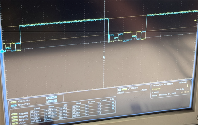
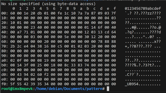
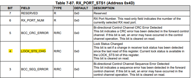
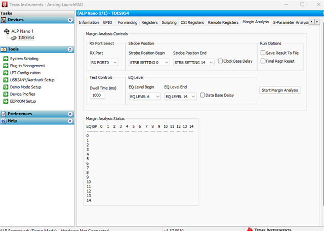
I am working on getting a TDES954/TSER953 combo working for a camera. I can retrieve the camera, TDES, and TSER i2c addresses individually but I cannot get the V3link to output i2c or even output at all, but just want to check verify i2c can get through V3 link. Would it be possible to give a list of registers to change from default to get this working for my application?
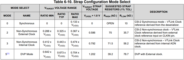
Mode = CSI-2 SYNC

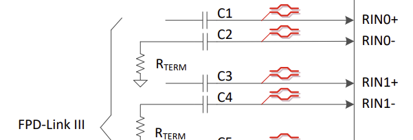
Shielded Twisted Pair

  • Hello Austin,

    If you can talk to each device through a local I2C connection, then it seems all devices are powered-up properly. 

    Is your main problem that you can't communicate with a remote device through the V3Link channel?

    For example, are you havingg trouble sending an I2C command from SoC -> TDES954 -> TSER953?

    Are you able to confirm if you have LOCK established on the TDES954 device? You can check this by going to the TDES954 and reading register 0x4D. Please note that this is an RX-Port specific register and you need to select an RX Port to read from first in register 0x4C.

    Are you also able to provide a register dump of the TDES954 and TSER953 devices?

    Best,

    Justin Phan

  • Thats correct we cant get anything from the V3 link just yet. 

    Here is the register dump

  • Hi Austin,

    From the register map, LOCK is not set.

    We expect 954 reg 0x4D = 0x03 on a successful link.

    I see that 954 reg 0x58 = 0xDE, which means the BC is the correct frequency. Can you share the 953 register dump? And can you share the resistors used on the MODE pin of the 953 device? I want to make sure that the serializer is in the same MODE setting as the deserializer.

    Also, this is a small note. Can you make sure that 954 reg 0x58 = 0x5E?

    You don't want to set bits 7 and 6 at the same time. You only want to set one of them at a time, with the most common use case setting the I2C_PASS_THROUGH bit only.

    This is not a direct reason for the I2C issue. You mainly need to get LOCK established first.

    Best,

    Justin Phan

  • We did just change the 954 register as both 7 and 6 were set high. 

    Here is the SER dump

  • Since I want CSI mode would having a crystal on the serializer make it so it wont work? I can depop it, I just realized I had a crystal on both the SER and DES.

  • Hello Austin,

    It doesn't matter if you put a crystal on the serializer in SYNC mode. In SYNC mode, the serializer will just ignore the local crystal and use the BC provided by the DES as its REFCLK.

    From these register dumps, I see that the 953 and 954 are in matching correct MODEs, but the LOCK is still not enabled. In that case, there are a couple possible causes:

    1. Maybe there is something on the V3Link channel that is causing issues. Can you share the connections you made from the IC to the connector on both the 953 and 954 boards?
      1. I mainly want to check if the capacitors are correct and if there is anything along the high-speed path that is suspicious.
      2. If you can send me the schematics for the 953 and 954 boards, that would be faster for me to check.
    2. Have you measured or simulated Insertion Loss and Return Loss on the high-speed channel?
      1. Maybe it's possible that the high-speed channel is lossy, which is causing the 953 and 954 to not be able to detect each other.
      2. Also, what cable are you using to connect the 953 and 954 boards together? What length and cable type?

    Best,

    Justin Phan

  • is there somewhere I can send this confidentially? 

  • You can email it to my work email:

    j-phan1@ti.com

  • Last update was that the DOUT+/- and RIN+/- traces are routed to USB Type-C connectors and cables. USB Type-C is nominally 85-Ohms (+/-10%) differential impedance, but the V3Link devices require 100-Ohms (+/-10%) differential impedance on the routing.

    Currently suspect that the impedance mismatch is preventing LOCK.

  • This is the DES without anything connected to the V3 link

    When I connect the Serializer it just looks like complete trash, basically noise. 

    One thing I thought as well was that since were using a STP do we have to change the i2c setting so that we use STP instead of Coax? It says something about strapping resistors can be used to do this automatically on the MODE pin but that didnt make sense to me since that dictates what mode the DES is going to be in. 

  • Hi Austin,

    What are you trying to measure here?

    The SerDes devices are bidirectional. Meaning that the serializer is outputting a 4Gbps (2GHz) signal and the deserializer is outputting a 50Mbps (25MHz - 50MHz) signal. The SER and DES devices also have 50-Ohms terminations at each receive port as well. If you power-up the deserializer and probe the RIN+/- pins with a differential probe that has 100-Ohms termination, then I expect that you should see a fluctuating signal, with a max frequency of about 50MHz.

    Also note that the signals are not clock signals. They are fluctuating, since they all contain data.

    There is no software setting to switch betwen STP or COAX mode. All that is required is a hardware change. You need to change the AC coupling capacitor on the RIN-/DOUT- trace to 15nF and add a 50-Ohms termination resistor at the RIN-/DOUT- trace.

    If you want to test COAX in your current hardware, you need to replace C2 with a 15nF capacitor. And find a way to terminate the RIN- line with a 50-Ohms resistor to GND.

    Best,

    Justin Phan

  • I was measuring the differential voltage at the Deserializer with nothing connected to make sure something was happening at least.

    the TDES954 data sheet says PORT_CONFIG address 0X6D details that you can switch between COAX_MODE and STP mode and the default value is made by a strap condition of mode pin is this not correct then?

    This what it looks like if I measure with differential probes at the AC coupling caps. my scope only goes up to 1GHz so I know I cant see the message properly by any means but Im assuming this is what youre meaning by the bidirectional communication?

  • Hello Austin,

    This is the DES without anything connected to the V3 link

    This is an image of what I kind of expect. If you turn on the measure frequency tool in your scope, it should read a fluctuating frequency that occasionally shows 50MHz. But it fluctuates since this is a data signal and not a clock signal.

    the TDES954 data sheet says PORT_CONFIG address 0X6D details that you can switch between COAX_MODE and STP mode and the default value is made by a strap condition of mode pin is this not correct then?

    This setting is not necessary to change.

    This what it looks like if I measure with differential probes at the AC coupling caps. my scope only goes up to 1GHz so I know I cant see the message properly by any means but Im assuming this is what youre meaning by the bidirectional communication?

    Make sure to only power one device, either the Ser or the Des, at a time. Otherwise, you will see 2 signals on top of each other.

    Best,

    Justin Phan

  • Hi justin,

    We figured out the issue was a strapping resistor I missed on the Serializer. It locks now. My camera outputs RAW10 data, does that mean I have to configure the TDES954 to be in RAW10 mode and the SER953 for DVP? Ive tried it with CSI mode and get a bunch of errors on the DES side. BIST mode appears to work just fine with no errors. 

  • Hello Austin,

    If you are using the 954/953, then the 953 has these MODE options

    You typically want to use Synchronous or Non-Synchronous mode if you are connected to a 954. You only use DVP mode if the deserializer is a DVP deserializer, such as the 914A/934.

    For the 954, also keep it in either Synchronous or Non-Synchronous mode. Do not use DVP mode.

    Both the serializer and deserializer must be in the same MODE.

    ...

    Which type of errors are you getting on the 954 side? Can you clarify which MODE setting is on the serializer, the deserializer, and provide the reg dump of the 954 again?

    Best,

    Justin Phan

  • both MODEs are set to CSI-2 Sync mode and the SERDES locks now. 

    Serializer Dump

    Deserializer dump

  • Hello Austin,

    Okay, are you able to send remote I2C commands from the SoC to the remote serializer or imager? And are you able to bring-up video? Both should be possible if you have LOCK now.

    Best,

    Justin Phan

  • Yes we can send i2C commands. But whats happening were not getting any MIPI data out. 

    Here is the MIPI into the SER

    Here is the V3 link data. 


    But when I probe the DES the MIPI lines are just held high no data.

  • It looks like from the i2c dump the serializer has pretty much very error possible

  • Is the imager correctly programmed to output video data?

    ...

    The TDES954 is not receiving any video data.

    954 reg 0x 73 - 0x74 = 0x00

    954 reg 0x 75 - 0x76 = 0x00

    ...

    From your scope screenshots, it looks like maybe the high-speed video data is coming into the serializer, but I am not certain since the amplitude of the HS MIPI data is roughly 200mV and it is a little difficult to tell. But here is what I typically expect the output to look like.

    If the MIPI lines are held high at the DES, then definitely no video is coming out there.

    ...

    Some things to check.

    1) Confirm if the imager has been programmed correctly.

    2) Confirm if all of the power rails to the 953 are at the expected values and that the Power-Up Sequence has been followed correctly.

    Make sure you are not sending any I2C commands until after at least 2ms after PDB is HIGH and after LOCK has been established.

    3) Can you confirm if you met 100-Ohms impedance control on the CSI traces between the image sensor and the 953 MIPI receiver? And if you correctly length matched the MIPI D-PHY traces?

    Best,

    Justin Phan

  • So we took the Imager out of the equation for now. When we do the random pattern generation from the Deserializer it looks very good. 

    But then when we try to do the Random pattern generator for the Serializer we just get a bunch errors.

    Here is the DES i2c dump

    My impedance is 93 ohms on the Deserializer matched within 1 mil. and the Serializer is 99 ohms matched to one mil. 

  • Also whats the expected voltage for LPF2 (pin12) on the Serializer? I was measure all the power pins and the 1.8V was ~1.75-1.8, and the 1.1 was 1.13-1.15, except LPF2 was 850mV. 

  • Hello Austin,

    If you read 954 reg 0x4D multiple times (maybe wait 1 second between each read), then does it always read out a value of 0x13?

    This register has multiple error flags that are cleared on read. I see that the flag for LOCK_STS_CHG is set.

    It might be set just due to power-up. But if you read 954 reg 0x4D multiple times and the error flag is not cleared, then that means that the deserializer is repeatedly losing LOCK with the serializer and you do not have a stable SerDes link.

    This means the high-speed channel between the SerDes is lossy and the SerDes devices cannot stably connect. This most likely goes back to how the differntial channel is 85-Ohms instead of 100-Ohms and this might be a design issue that requires a revision.

    LPF2 voltage will vary over operation. 850mV is not an unexpected value.

    Best,

    Justin Phan

  • on power up it was 0x33, but after doing antoher dump it changed to 0x03.

  • If you read 954 reg 0x4D multiple times, do you always get a value of 0x03?

    Wait a second between each read and check if the value of 954 reg 0x4D updates.

    Can you also run the MAP tool, to check the quality of the link? This can be done in the Margin Analysis tab in ALP

  • I dont have access to that since I dont have USB on my board. Is there a concern that PASS isnt working? Ive even tried BIST, and it locks but PASS stays low.

  • The concern is that you are getting unstable LOCK due to excess loss on the high-speed channel between the Ser and Des. By default, LOCK and PASS are linked together and they are both HIGH in the previous register dump. I am recommending 2 next steps.

    1) Read 954 reg 0x4D multiple times. Do you always get a value of 0x03? If you do not consistently get a value of 0x03, then that means LOCK is unstable because the error flag that LOCK is lost keeps getting set. If LOCK is lost, then you are intermittenly losing video data, which explains a lot of the errors you are seeing.

    2) If you cannot run MAP on your system, then you have to measure or simulate the Insertion Loss or Return Loss across your high-speed channel and make sure it is within the limits defined by TI.

  • We are getting 0x03 5 times in a row with about 10s in between.

  • Do you happen to have a UART to I2C converter tool, such as a USB2ANY or an Aardvark, which can connect an external lab PC to the local I2C bus of your system?

    It would help a lot if you can run the MAP program on a lab PC, since I assume right now, you are doing the software bring-up through an SoC.

    ...

    Possibilities right now:

    1) Maybe LOCK is up, but the link is still lossy enough to cause bit errors in the video data sent over the cable (as indicated in 954 reg 0x4E).

    - To confirm if this is true or not, you need to find a way to run MAP. Or measure/simulate Insertion Loss and Return Loss on your high-speed channel.

    2) Maybe the PATGEN on the serializer is not setup properly. Maybe some I2C commands were lost over the cable due to high loss in the FC or BC frequency ranges, which corrupts some of the I2C writes.

    - To confirm this, you can connect an I2C Master directly to the serializer PCB's I2C bus and program PATGEN from there.

  • I just order a USB2ANY and ill try it tomorrow. Can you tell me what the PASS criteria are? 

  • Pass is an optional signal. The source for HIGH/LOW is programmable and defined in  PORT_PASS_CTL (Address 0x7D) in the TDES954. By default, it is tied to LOCK.

  • For the BIST mode we copied what the example had and when we try to write an error injection it doesnt do anything. Only difference I see between what the example has and what we have is that pass is high, does PASS need to be high to do error injection?

    Devices Reset
    954 Device ID (0x00): 0x60
    953 Device ID (0x00): 0x30
    ------------------------------------------------------------------
    Reciever Lock Status (0x04): 0xdb
    Should read 0xDF
    ------------------------------------------------------------------
    Read BCC Error Status (0x79): 0x0
    Consult Register 0x79 on the SER for more information
    ------------------------------------------------------------------
    Pre-Error Link Status of 953 (0x52): 0x45
    Should read 0x45 = RX Lock Detect, HS PLL Lock, Link Detect
    ------------------------------------------------------------------
    BIST CRC Error count (0x54) on 953 before forced error. 0x0
    ------------------------------------------------------------------
    Read BIST CTL register (0xB3) Before BIST ENABlED 0x0
    Should read 0x00 or 0x08


    Read BIST CTL (0xB3) register After BIST ENABLED 0x1
    Should read 0x01
    ------------------------------------------------------------------
    Read BIST Lock Status Change of 954 RIGHT AFTER BIST enabled (0x4D): 0x13
    Read to clear BIST enable Lock Status Change.
    Read Post-BIST Lock Status Change of 954 RIGHT BEFORE BIST disabled (0x4D): 0x10
    Should read 0x03, If lock status changed during BIST, will read 0x13
    ------------------------------------------------------------------
    Post-Error Link Status of 953 (0x52): 0x45
    Should read 0x4D = RX Lock Detect, HS PLL Lock, Link Detect, and BIST CRC Error
    Reciever Lock Status (0x04): 0xdb
    Should read 0xDF
    ------------------------------------------------------------------
    BIST CRC Error count (0x54) on 953. 0x0
    Parity Error count MSB (0x56) on 954. 0x0
    Parity Error count LSB (0x55) on 954. 0x0

  • This is the script we ran

    BIST_953_954_WithForcedError.py
    Revision 1.1 June 13, 2017

    Modified minimally for:
    - Python 3
    - Debian /dev/i2c-1 using smbus / smbus2
    """

    import time

    # Try smbus2 first (better repeated start handling), fall back to smbus
    try:
       from smbus2 import SMBus
    except ImportError:
       from smbus import SMBus


    class BoardI2C:
       """
       Minimal wrapper to emulate original board.WriteI2C / board.ReadI2C API.
       Assumes 7-bit I2C addresses as given in the original script.
       """

       def __init__(self, bus_num=1):
           self.bus = SMBus(bus_num)

       def WriteI2C(self, dev_addr, reg, value):
           """Write single byte to register."""
           value &= 0xFF
           try:
               self.bus.write_byte_data(dev_addr, reg, value)
           except Exception as e:
               print(f"WriteI2C error: addr=0x{dev_addr:02X} reg=0x{reg:02X} val=0x{value:02X} ({e})")

       def ReadI2C(self, dev_addr, reg, length):
           """
           Read from device.
           If length == 1 returns single integer (to match original usage).
           Otherwise returns list of integers.
           """
           try:
               if length == 1:
                   return self.bus.read_byte_data(dev_addr, reg)
               else:
                   data = self.bus.read_i2c_block_data(dev_addr, reg, length)
                   return data
           except Exception as e:
               print(f"ReadI2C error: addr=0x{dev_addr:02X} reg=0x{reg:02X} len={length} ({e})")
               if length == 1:
                   return 0x00
               return [0x00] * length


    def main():
       print("\n\n")

       board = BoardI2C(bus_num=1)

       # Define 954 and 953 Addresses
       UB953 = 0x09  # 953 SER Alias ID, check 0x5C on 954 for confirmation
       UB954 = 0x30  # 954 Device ID, check 0x00 on 954 for confirmation

       # Digital Reset except for registers
       board.WriteI2C(UB953, 0x01, 0x01)  # Resets 953
       time.sleep(0.5)
       board.WriteI2C(UB954, 0x01, 0x01)  # Resets 954
       time.sleep(0.5)

       print("Devices Reset")

       # Confirm Devices can communicate with each other
       print("954 Device ID (0x00):"hex(board.ReadI2C(UB954, 0x00, 1)))  # Should be 0x7A
       time.sleep(0.5)
       print("953 Device ID (0x00):"hex(board.ReadI2C(UB953, 0x00, 1)))  # Should be 0x30

       print("------------------------------------------------------------------")
       time.sleep(0.5)

       # Read Receiver Lock Status
       print("Reciever Lock Status (0x04):"hex(board.ReadI2C(UB954, 0x04, 0x1)))  # DEVICE_STS
       print("Should read 0xDF")

       print("------------------------------------------------------------------")
       time.sleep(1)

       # Enable write for Port0 of FPD3_PORT_SEL
       board.WriteI2C(UB954, 0x4C, 0x01)

       # Clear Errors and Error Count
       board.WriteI2C(UB953, 0x49, 0x28)  # BC_CTRL selects BIST_CRC ERR CLR and CRC ERR CLR

       print("Read BCC Error Status (0x79):"hex(board.ReadI2C(UB953, 0x79, 1)))
       print("Consult Register 0x79 on the SER for more information")

       print("------------------------------------------------------------------")

       print("Pre-Error Link Status of 953 (0x52):"hex(board.ReadI2C(UB953, 0x52, 1)))
       print("Should read 0x45 = RX Lock Detect, HS PLL Lock, Link Detect")

       print("------------------------------------------------------------------")

       print("BIST CRC Error count (0x54) on 953 before forced error.",
             hex(board.ReadI2C(UB953, 0x54, 1)))

       print("------------------------------------------------------------------")

       time.sleep(1)

       # Enabling BIST, Error, and Lock-Change Status
       print("Read BIST CTL register (0xB3) Before BIST ENABlED",
             hex(board.ReadI2C(UB954, 0xB3, 1)))
       print("Should read 0x00 or 0x08\n")

       board.WriteI2C(UB954, 0xB3, 0x01)  # Enable BIST

       print("Read BIST CTL (0xB3) register After BIST ENABLED",
             hex(board.ReadI2C(UB954, 0xB3, 1)))
       print("Should read 0x01")

       time.sleep(0.25)
       print("------------------------------------------------------------------")
       print("Read BIST Lock Status Change of 954 RIGHT AFTER BIST enabled (0x4D):",
             hex(board.ReadI2C(UB954, 0x4D, 1)))
       print("Read to clear BIST enable Lock Status Change.")

       # Force 1 Error
       board.WriteI2C(UB954, 0xD0, 0x01)  # PORT_DEBUG register

       # Uncomment for continuous errors:
       board.WriteI2C(UB954, 0xD0, 0x02)
       time.sleep(10)
       # If forced continuous errors, stop forcing:
       board.WriteI2C(UB954, 0xD0, 0x00)

       print("Read Post-BIST Lock Status Change of 954 RIGHT BEFORE BIST disabled (0x4D):",
             hex(board.ReadI2C(UB954, 0x4D, 1)))
       print("Should read 0x03, If lock status changed during BIST, will read 0x13")

       # Disable BIST and Port0
       board.WriteI2C(UB954, 0xB3, 0x00)
       board.WriteI2C(UB954, 0x4C, 0x00)

       print("------------------------------------------------------------------")
       time.sleep(1)

       # Check if Error(s) occurred
       print("Post-Error Link Status of 953 (0x52):"hex(board.ReadI2C(UB953, 0x52, 1)))
       print("Should read 0x4D = RX Lock Detect, HS PLL Lock, Link Detect, and BIST CRC Error")

       print("Reciever Lock Status (0x04):"hex(board.ReadI2C(UB954, 0x04, 0x1)))
       print("Should read 0xDF")

       print("------------------------------------------------------------------")

       print("BIST CRC Error count (0x54) on 953."hex(board.ReadI2C(UB953, 0x54, 1)))
       print("Parity Error count MSB (0x56) on 954."hex(board.ReadI2C(UB954, 0x56, 1)))
       print("Parity Error count LSB (0x55) on 954."hex(board.ReadI2C(UB954, 0x55, 1)))

       print("------------------------------------------------------------------")

       # Clear BIST Errors on 953
       board.WriteI2C(UB953, 0x49, 0x28)

       print("\n\n")


    if __name__ == "__main__":
       main()

  • Pass will not cause operation of the device to fail. It is a register that is programmed to output a status. This status can be used to do things such as discard data or enable an interrupt, but all of these functions are disabled by default.

    Since you are using USB-C, then the cable and connector are still 85-Ohms, which can cause data loss due to the impedance mismatch.

    It is possible that either I2C commands are being lost, which cause remote devices such as the serializer or imager to not be programmed correctly and cause issues in the generated data. Or the high-speed channel is lossy enough to cause video data errors.

    One thing you can do is share the PATGEN script you used for the serializer. Then, share the serializer reg dump to ensure the registers were written correctly.

    Or, you have to simulate or measure the S-Parameters across the high-speed channel and confirm the Insertion Loss and Return Loss characteristics.