DP83869HM: No output on REF_CLK and no Power on VDDA1P8 in 2 power mode

Part Number: DP83869HM
Other Parts Discussed in Thread: DP83869

Tool/software:

Hi I am having difficulty with the DP83869. I am able to communicate over MDIO but I am not able to establish comms. 

The first suspicious thing we noticed is that there is no clk on ref_clk. Even though the mode reported is RGMII to copper

The below shows that we read the strap mode to be RGMII to copper and that the address is 0x3

root@taquito-tfc:/data$ ./mdio-ext read 0x6e
reading reg: 0x6e
0x0030

The next weird thing we noticed is that the PWD_DWN is high unless we override it over MDIO. 

root@taquito-tfc:~$ mdio stmmac-1 3 0
0x1940

Here is a picture of our circuit

Strapping should be for RGMII to Copper (which we are reading properly over MDIO). 

PWDN is pulled up as it is active low

Reset is also pulled up as it is active low

Once we override the pwd_dwn pin over mdio, we are still reading the CORE_PWR_MODE register to be all 0


I am curious if anyone has experience using 2 power mode with VDDIO being 1.8V? As another thing we are noticing is that the VDDA1P8 pins are measuring to be 0V

  • Hi,

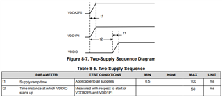
    Have you checked the power sequence between the 1.1V and 2.5V supply? I wanted to make sure that the power sequencing requirements were being followed. As put in the datasheet, when in 2-supply mode, both supplies must power on at the same time, or if that is not feasible, the following sequence must be used.

    Thanks

    David

  • Here is the sequence of power. It seems to match the specification

  • Hi,

    I agree with you that the power up sequence looks ok. 

    With register 0x6E being an extended access register, are you using extended register read method to read it?

    Are you able to link up in this particular case? 

    If you remove the 10k pulldown on CLK_OUT, are you able to measure the output clock? 

    When you say REF_CLK, I assume you mean RX_CLK, and not XI and XO?

    Also, looking at the schematic, please do not short the center tap of the transformer together.  Each center tap on the side connected to the PHY, must be isolated from one another and connected to ground via a decoupling capacitor (0.1µF recommended).

    Thanks

    David

  • Yeah referring to RX_CLK sorry for the confusion. I can try to remove the 10k pull down on clk_out. But I am not sure that will change anything because we are able to measure a 25Mhz signal on clk_out fine.

  • Hi,

    Thanks for the clarification. The RX_CLK is the recovered receive clock. The MDI has to be up before you can see the RX_CLK. 

    With the CLK_OUT at 25MHz, it appears the PHY is alive. 

    With the read of register 0x6E, we can verify the PHY is being configured correctly.

    And then we can verify when the link is up, you will see the RX_CLK.

    Thanks

    David

  • I think you are right about all the center taps being grounded as an issue. I will try to find an rJ45 connector with the capacitors built in to swap