Other Parts Discussed in Thread: LM2841
Tool/software:
Dear TI circuit wizards,
Help! I'm running into an issue that has been giving us woes for a couple weeks now and seemingly have been able to narrow down its source to communication between the host microcontroller/CAN controller and the TCAN3414 transceiver. Basically, this circuit is a mixed-signal measurement system that measures timing by blowing tiny signals up into square waves, and has a LOT of gain on the analog side (>50dB). Additionally (unfortunately) in this version of the circuit, the very first functional block in the analog signal chain has essentially no power supply rejection (think common emitter single BJT kind of structure). So if there's any frequency that ripples in the power supply that happens to be in the frequency range of interest, we start having issues, especially because the analog circuit has AM envelope detection.
But in theory all digital devices whose current draw transients might cause ripple operate at a much higher frequency, or so we thought.
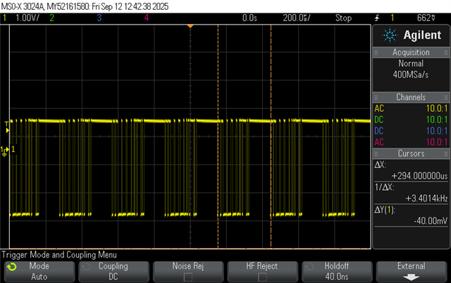
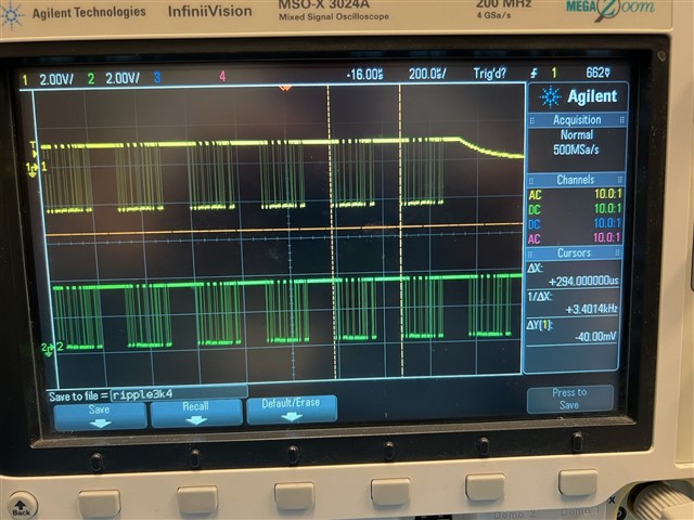
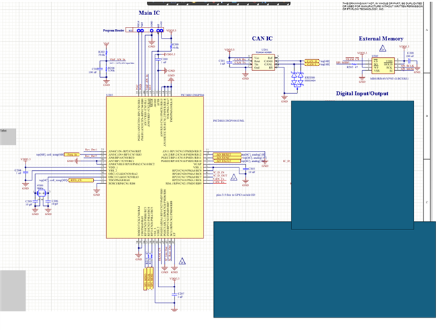
This is the first time a product in our family of devices has used a TCAN3414. Previous versions have used a 5V CAN transceiver (SN55HVD251DRJR) with no issues, but these designs also happen to be significantly lower gain and generally have better PSRR (as well as different current consumption specs). In the problem child design, it seems that whenever the host microcontroller has basic code in place (that I did not write, but can get access to information if necessary) to communicate with the TCAN, this extremely consistent 3.4kHz ripple appears in the power supply, which sits right in the middle of our analog frequency range of interest. I'm attaching snippets of the schematic below to help illustrate. The TCAN is powered by the 3.3V rail pictured below, by way of input voltage (9-30V) switched down with an LM2841 to about 6V, then run through two linear regulators (the 3.3V regulator is in series with the 5V regulator). 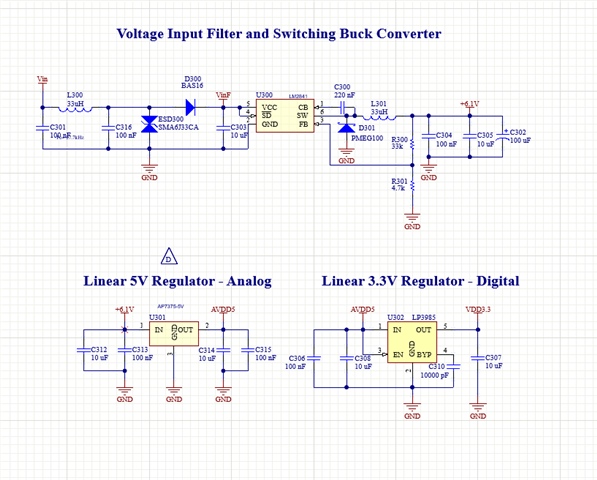
This design resides in a small ROHS compliant 4-layer FR-4 PCB with the following (copper) stackup:
1) Bottom Copper (this is where all the sensitive analog circuitry is)
2) Ground plane (unbroken)
3) Reference plane (segmented)
4) Top Copper (this is where nearly all digital ICs reside - worth noting the CAN chip is pretty much as far as physically possible from the analog circuitry)
I have considered and investigated the following failure modes:
- Maximum current draw exceeded: SMPS. LM2841 limit is 300mA per the datasheet, and system current draw is around 100mA, so this is not our problem.
- Saturation current reached: SMPS inductor. API Delevan S1210R-333K has a maximum current rating (note - not saturation current, which is not specified) of 189mA. Again, the system current draw sits right around 100mA during normal operation. I even tried a similar inductor (SP1210R-333K) with a higher max current rating of 243mA just in case - no significant difference. Maybe a tiny, tiny amplitude difference. This seems unrelated to the issue.
- Maximum current draw exceeded: 3.3V LDO (LP3985IM5-3.3/NOPB). This does seem like a possible factor. Limit is 150mA, worst case currents (assuming no bus fault) total to 141mA (MCU running at 48MHz, effectively 24MIPS, so current draw from the datasheet is max at +85C, the max temperature this device will be used at). With a bus fault, this would add another 70mA to current draw, so I could see this possibly being an issue, but I am no CAN expert. Our firmware guy says there hasn't been any bus fault behavior in typical usage, and I see the 3.4kHz with and without the CAN lines connected and terminated. It's possible current peaks are jumping past that 150mA limit.
- Maximum current draw exceeded: 5V LDO (AP7375). This seems unlikely. This LDO has a max current draw of 300mA, and the analog measurement side of things draws only a handful of mA, less than 50.
- SMPS control loop stability - lowered integrator gain, added feedforward capacitance, changed nothing about the 3.4kHz ripple
- Considering how low frequency the ripple is, I removed the 100uF from the 6V rail to see if it affected oscillation frequency at all - it didn't. I added 100uF to the 3.3V rail as well, for fun. No change.
- Communication with the TCAN chip. When our bootloader is wiped from the MCU, the ripple immediately disappears, and the only thing in the bootloader is code to facilitate CAN communication. I also used an Xacto knife to cut the power delivery trace to the TCAN chip and the ripple immediately went away. I also at one point cut the connection between the 5V and 3.3V LDO and the ripple went away as well, so something on the 3.3V rail is causing this issue for sure.
Any help here appreciated. It seems to me this 3.4kHz issue either is a result of the communication between the MCU and the TCAN3414 transceiver, or a result of the increased current draw from this communication, but I could be missing something right in front of my face. The 3.4kHz periodicity of the ripple and how ruthlessly consistent it is must be some kind of hint, right? Please let me know if there is more information I can provide (baud rates or whatever), and thank you in advance for the assistance!
Best,
Nathan
PS In parallel I'm gonna see if I can grab a pin-for-pin 3.3V LDO with a higher current output, see if that makes a difference. Will report back.