This thread has been locked.

If you have a related question, please click the "Ask a related question" button in the top right corner. The newly created question will be automatically linked to this question.

DP83848Q-Q1: How to bring-up an RMII 100BASE-T design

Part Number: DP83848Q-Q1
Other Parts Discussed in Thread: DP83826AEVM, DP83848K-MAU-EK

Tool/software:

Hello,

I just implemented my first Ethernet design using this chip with RMII interface and 100BASE-T MDI implementation (magnetics, diode array). At first attempt with an Ethernet dongle, there are no link lights and no disernable waveforms on the two wire pairs.

This is my first design so I'm not totally sure about the steps and process to bring up the design. What signals to look for.

Thanks,

Wilson

  • Hi Wilson,

    I'd like to preface that DP83848 is an older part that has been superseded by DP83826A. That being said, lets do some basic health checks to narrow down your issue:

    • Is the device powered correctly with 3.3V on IOVDD and AVDD?
    • What sort of ethernet dongle are you using, and are you able to test without a dongle in the signal path?
    • Do you have register access via MDC/MDIO?
    • Can you show the clock signal at X1 and the CLK_OUT pins? I'd like to make sure your clock is correct.

    Best,

    Shane

  • Thanks for your reply! I have it configured in RMII so I'm using a 50MHz osc that fans to both PHY and MAC. I checked correct +3.3V at power inputs. 

    I think, right now, I'm trying to figure out MDC/MDIO. We're working with a Linux-based system so we didn't think through the driver changes we'd need on the processor/MAC side. 

    Is there a way to fully understand how a MAC-PHY pair starts up, particularly with this PHY? For example, what are the general data communication steps that happen and what messages are sent / what registers need to be set and how? Is there a resource I can reference?

    Thanks,

    Wilson

  • Hi Wilson,

    Is there a resource I can reference?

    We have a Debug guide with Linux on DP83848 product page.

    While it is not 1:1 with DP83848, we do have a DP83826A troubleshooting guide. At a high-level this may be useful for debugging an RMII or MDI interface.

    Is there a way to fully understand how a MAC-PHY pair starts up, particularly with this PHY?

    The MAC and PHY do not exactly start up as a pair. For the most part, the PHY is independent of the MAC and will simply translate between ethernet MDI and RMII data. Getting a link up on the MDI (Ethernet) side of the PHY does not even require a MAC to be connected at all. Some of our EVMs (such as DP83826AEVM) do not have a MAC, yet can still link up over the RJ-45 connection.

    For example, what are the general data communication steps that happen and what messages are sent / what registers need to be set and how?

    Typically the first step is to get a link up on the Ethernet side. This should not require register writes if your strap settings are correct. The most relevant strap would be AN_0 (LED_LINK) for auto negotiation ability. You can see the strap settings in section 3.8 of the datasheet.

    If you aren't able to get a link I would check that your PHY is alive and you can access the MDC/MDIO bus. If you can get the MDC/MDIO bus working, the PHY itself is likely ok. If you have accessible MDC/MDIO lines a direct way to test this bus is to use an MSP430 Launchpad with TI's public USB2MDIO software to emulate an MDIO controller. 

    If you are able to access MDC/MDIO but still cannot get a link on the RJ-45 then there may be an issue with the MDI-side implementation. 

    Best,

    Shane

  • Hi Shane,

    Thanks for the information. It was helpful and I was able to quickly figure out that I had made a schematic error at the TVS diode array and the TXD+/- and RXD+/-. I did a quick rework and was able to get the PHY to auto-negotiate with the Ethernet dongle. I was able to see the link status bit assert by scoping out a status reg read packet on the MDIO and MDC lines.

    Beyond that, I wasn't able to establish Ethernet communication. Part of the problem was I had very limited firmware support today and I hope tomorrow will be different. Are there any obvious next debugging steps to verify the connection between the MAC and PHY? What should I send from either side and what would the RMII packets look like?

    Thanks,

    Wilson

  • Hi Wilson,

    The first method we use to test the RMII interface is a loopback test. In this loopback test, the PHY takes data received from the MAC and transmits it back to the MAC. 

    You can send any type of packets from the MAC and check that you are receiving these same packets error-free back on the MAC. If you notice the packets are coming back with errors, there is likely an issue with the RMII interface. Can you try performing the loopback test?

    The RMII data and clock signals should look similar to the image below (taken from DP83826A troubleshooting guide).

    If you suspect the issue is on the RMII interface the most common issues are:

    • Poor length matching on data and clock traces.
    • Violation of the setup and hold times between the clock and data signals
    • Poor high speed trace routing (stubs, sharp bends, etc...) 

    Best,

    Shane

  • Hi Shane,

    I need to back up a bit because it seems like my auto negotiated link between the PHY and dongle are not as stable as I thought. In fact, something changed yesterday where I haven't been able to get a good link. Some more basic questions:

    • I have the PHY strapped to auto MDIX/MDI enabled with auto negotiation enabled as well. What signals should I be seeing during Auto MDIX, as well as during auto negotiation? I'm a little confused about the 100ns link pulse vs FLP.
    • What signal amplitudes should I be seeing on the MDI lines? ie. what should be the correct amplitude for the link pulses, FLP, MLT3, etc.?
    • When probing the failed, inactive link, I saw that my DUT was putting MLT3 signals on the TX pair. However, the RX pair had nothing. What does this suggest? 
    • I'm still confused about the center tap (PHY side) implementation at the isolation Xfmr. There are designs with connection to 3V3 with bypass 0.1uF to GND and there are ones that do not. I saw something about it being a difference between current mode vs voltage mode PHYs. How do I know if a PHY is current or voltage mode? ie. what is the DP83848?
    • Similarly, I also see different Bob Smith termination designs for the RJ45 side of the magnetics. Some schematics show a connection to Earth while others show connection to board signal GND. Furthermore, the capacitor value is often 1 - 2 nF but I also see some schematics (including in TI Precision video) where it is 10nF. What is the impact of this cap value and what determines it?

    Thanks for entertaining my questions. Feel free to direct me to literature where applicable.

    Thanks,

    Wilson

  • Hi Wilson,

    The relevant source of information here would be the IEEE802.3 spec and the DP83848 datasheet. I'll try and summarize below:

    What signals should I be seeing during Auto MDIX, as well as during auto negotiation? I'm a little confused about the 100ns link pulse vs FLP.

    Depending on whether you are forcing 10M speeds only or auto negotiating 10/100 speeds you will see either the normal link pulse or fast link pulse

    Since you have auto negotiation enabled I would expect fast link pulses when first connecting the device. FLP is just a rapid burst of 100ns link pulses. This is described in section  28.1.1 of the IEEE802.3 spec

    What signal amplitudes should I be seeing on the MDI lines? ie. what should be the correct amplitude for the link pulses, FLP, MLT3, etc.?

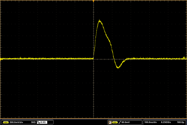
    For link pulses the signal should look similar to the image below (taken from our DP8382x compliance guide) I see the amplitude in this case is around 2Vpp

    In general the link pulse needs to pass a IEEE802.3 defined template in order to be considered valid. Not all link pulses will have the same amplitude, but they should have a similar shape. Please refer to Figure 14–13 in the IEEE802.3 spec for details on this template.

    When probing the failed, inactive link, I saw that my DUT was putting MLT3 signals on the TX pair. However, the RX pair had nothing. What does this suggest? 

    By 'failed' link do you mean the link was down entirely, or are you passing data with errors? It sounds like the TX was working but you aren't receiving signals from the link partner if the RX pair has nothing.

    How do I know if a PHY is current or voltage mode? ie. what is the DP83848?

    I strongly recommend following the datasheet implementation for this device. I believe DP83848 is a current mode driver. This does affect the implementation, but often a PHY manufacturer will provide a reference circuit to show correct implementation:

    What is the impact of this cap value and what determines it?

    The bob smith termination is used to impedance match across the ethernet cable. Typically what determines it is testing, and certain applications may change the recommendation (for example PoE vs no PoE).

    Best,

    Shane

  • Hi Shane,

    Thanks for your continued responses. 

    Since you have auto negotiation enabled I would expect fast link pulses when first connecting the device. FLP is just a rapid burst of 100ns link pulses. This is described in section  28.1.1 of the IEEE802.3 spec

    I do see FLP pulses on both TX and RX MDI lines when the board is connected to the USB-Ethernet dongle. When zoomed out, I can see the pulses spaced apart as illustrated. The first three are spaced apart by 62.5us and subsequent pulses are 125us apart. I'm not sure why there are two different spacings.

    For link pulses the signal should look similar to the image below (taken from our DP8382x compliance guide) I see the amplitude in this case is around 2Vpp

    Is this scope shot supposed to be differential? If so, I think I do get something like that. For a pair, I would get a large amplitude on the P line and the same pulse but with smaller amplitude on the N line. The difference of them (I only have single ended probes) appear to subtract to somewhere between 1 - 2 Vpp in amplitude (using math function on the scope).

    I found this odd because I thought P and N were supposed to be fully complementary signals but I guess that's not supposed to be the case?

    In general the link pulse needs to pass a IEEE802.3 defined template in order to be considered valid. Not all link pulses will have the same amplitude, but they should have a similar shape. Please refer to Figure 14–13 in the IEEE802.3 spec for details on this template.

    Unfortunately, I can't get access to the spec document...

    I strongly recommend following the datasheet implementation for this device. I believe DP83848 is a current mode driver. This does affect the implementation, but often a PHY manufacturer will provide a reference circuit to show correct implementation:

    Initially, I had forgotten to tie 3V3 to the center tap/bypass cap. I have reworked that on the boards.

    I'm not sure why the auto negotiation is no longer working, especially when it had worked before. Per my comments above, I feel like I'm seeing the correct FLP signatures but there are some open questions regarding what I'm seeing. I'm not sure what my next steps should be.

    Thanks,

    Wilson

  • Hi Wilson,

    The first three are spaced apart by 62.5us and subsequent pulses are 125us apart. I'm not sure why there are two different spacings.

    I believe what you're seeing is the spacing between clock pulses and data pulses. During auto negotiation both the clock and data are communicated through fast link pulses. You can see in the datasheet that Clock pulses are separated by 125us and a clock pulse to a data pulse will be separated by 62us.

    Is this scope shot supposed to be differential?

    Yes that scope shot is differential. I tested this in our lab on DP83826 and saw a similar waveform to what you describe (yellow is + blue is -)

    I'm not sure why the auto negotiation is no longer working, especially when it had worked before. Per my comments above, I feel like I'm seeing the correct FLP signatures but there are some open questions regarding what I'm seeing. I'm not sure what my next steps should be.

    Since this is an auto negotiation issue, we can narrow the problem down to the MDI side implementation, the cable, or the link partner. The MDI is a sensitive portion of any design due to the high speed of MDI signals. I have a few questions and steps we can take to check the MDI-side connection.

    • Is there anything in your design that might compromise the signal integrity on the MDI side of DP83848? Try to eliminate stubs in the trace and ensure you're keeping MDI traces length matched, impedance matched, and as short as possible.
    • Can you try different ethernet cables or removing the ethernet dongle when testing?
    • Can you test with a different link partner?

    Best,

    Shane

  • Hi Shane,

    You can see in the datasheet that Clock pulses are separated by 125us and a clock pulse to a data pulse will be separated by 62us.

    I see it and it makes sense. I'm guessing if there's a pulse at 62us spacing, it's a 1 and full 125us spacing means it's a 0? Is there a spec that describes what that full FLP burst is sending and what data packet is supposed to look like?

    I tested this in our lab on DP83826 and saw a similar waveform to what you describe (yellow is + blue is -)

    First, I probed the output of the Ethernet dongle via my custom breakout cable. I observed a similar waveform to you but the amplitude was different. There's also a more pronounced lower step. The peak amplitude for both TX+ and TX- was approx +1.5V and -1.6V, respectively, which gave the differential trace a full amplitude of 3V. I'm not sure if this is correct but I did verify the operation of the dongle separately.

    After that, I probed the output of my board (DP83848 TX+/- after the magnetics). I observed a similar profile but the amplitudes were a fair bit higher. TX+ and TX- were +2.1V and -2.4V, respectively, yielding a differential amplitude of 4.5V.

    Happy to provide scope shots but I can't seem to paste any images here.

    Since this is an auto negotiation issue, we can narrow the problem down to the MDI side implementation

    Agreed. That's what I've been focused on today. I found that the CM installed the magnetics on backwards but after corrective rework, the problem was not fixed. The probing I described above was after the rework.

    I ordered a DP83848K-MAU-EK eval board to have an extra DUT to test with and compare against. Otherwise, I could connect it to a different link partner. I have been using two different USB-ethernet dongles, which I have verified by linking together. I've also purchased some CAT5e cables with only two wire pairs to limit activity during auto-negotiation.

  • Hi Wilson,

    Is there a spec that describes what that full FLP burst is sending and what data packet is supposed to look like?

    The IEEE802.3 spec would describe the full structure of auto-negotiation. If you're concerned about the link pulse I recommend running a compliance test on the RJ-45 port. Ethernet PMA compliance tests will measure the link pulse to ensure it fits the IEEE defined template. 

    I observed a similar profile but the amplitudes were a fair bit higher. TX+ and TX- were +2.1V and -2.4V, respectively, yielding a differential amplitude of 4.5V.

    This is interesting as the link pulse should be under 3.1V. Are the TX+/- and RX+/- pairs terminated with 100ohms differential in your measurements or are they just broken out in your cable? Incorrect terminations will show different amplitudes.

    Happy to provide scope shots but I can't seem to paste any images here.

    Images can be added using the Insert -> image/video/file function in the bottom of the E2E text box. In the next window, click the 'upload' button (appears as grey text under the File/URL text field):

    I ordered a DP83848K-MAU-EK eval board to have an extra DUT to test with and compare against.

    This is a good idea. Testing different link configurations can help us narrow down where the link is breaking down in your setup.

    Best,

    Shane

  • Hi Shane,

    After wrestling with the hardware for a while, we finally got it working. I'm not sure what exactly I was fighting but it appears to be a combination of the misrouted MDI lines, rotated transformer, and unreliable connection of our PCBA breakout cables. We were also able to switch to a pre-written driver for our embedded system and the MAC side of the chain worked out of the box after the auto-neg problems were resolved.

    This is interesting as the link pulse should be under 3.1V. Are the TX+/- and RX+/- pairs terminated with 100ohms differential in your measurements or are they just broken out in your cable? Incorrect terminations will show different amplitudes.

    Per your comment, I measured this from the contacts of the RJ45, so it was unterminated, which affected the amplitude but I'm not sure how. With both link partners electrically connected, the auto neg pulse amplitudes were < 3Vdiff.

    Question: I'm going to re-spin my board with my findings. Can you tell me which power rail should the termination resistors and transformer center tap be tied to? DP83848 has AVDD33 and IOVDD33.

    Thanks,

    Wilson

  • Hi Wilson,

    Glad to hear you've got it working! The MDI is sensitive so it makes sense the trace routing or transformer could stop a link from establishing.

    Can you tell me which power rail should the termination resistors and transformer center tap be tied to?

    These should be tied to either AVDD33 or IOVDD33. Designs like our DP83848-MAU-EVK even tie AVDD33 and IOVDD33 to the same rail.

    I'll mark this as resolved for now, but let me know if you have any more questions and I will continue to reply here.

    Best,

    Shane

  • Thanks for your help, Shane.