This thread has been locked.

If you have a related question, please click the "Ask a related question" button in the top right corner. The newly created question will be automatically linked to this question.

TCAN1051-Q1: We get error frame when TCAN1051 is in the dominant state

Part Number: TCAN1051-Q1
Other Parts Discussed in Thread: TCAN1051

Tool/software:

Hi Expert,

My customer is doing communication test as below, but they get error frame sometimes, please help to analyze and give some suggestions.

  • There are 9 nodes on the CAN BUS, the length of the BUS is 8m, and the baud rate is 2Mbps. 
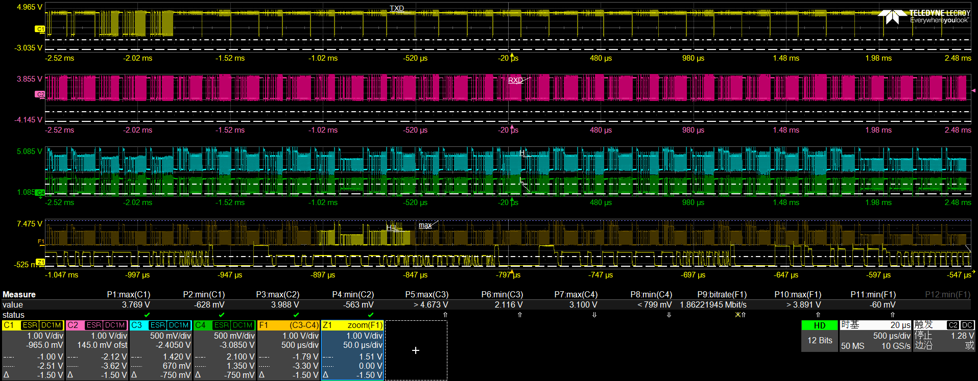
  • When TCAN1051 is in the recessive state we could see that the CANH-CANL is about 2.2V, however, when TCAN1051 is in the dominant state we could see that the CANH-CANL is nearly 1.5V or lower, which we think is the main reason we get such error frames.

  • What are the possible reasons for the error frame? How to solve?
  • Besides, we notice that this issue is more easily gotten when a large volume of data is transmitting by TCAN1051, what's the source current of TCAN1051 CAN dominant?

Best Regards,

Jack Li

  • Hi Jack, 

    I suspect this is most likely caused by the star topology with long stubs at 2 Mbps causing reflections and the reduced dominant differential VOD. This can be verified when the data rate is reduced to 500 kbps / 1 Mbps. If error vanishes, it should confirm the topology concern.

    I would recommend to rewire with a linear bus for < 0.3 m stubs. 
    if rewiring is not feasible, include dampening resistors of about 33 ohms at the IC pins, use split terminations, and reduce the number of simultaneous active nodes to verify, thanks. 

    Best Regards,

    Michael. 

  • Hi Michael,

    if rewiring is not feasible, include dampening resistors of about 33 ohms at the IC pins,

    Thanks for your kindly reply. Could you please clarify about how to add the 33 ohms at the IC pins. We have added the 120Ω terminal resistor, can we change it? 

    Besides, I wonder why the CANH-CANL is about 2.2V when TCAN1051 is in the recessive state but the CANH-CANL is nearly 1.5V or lower when TCAN1051 is in the dominant state, thanks.

    Best Regards,

    Jack Li

  • Hi Jack,

    This is not pertaining to the termination resistor. The bus should always include the overall 60 ohms bus impedance for optimal performance (I.e., the two 120 ohms at the end of the bus).

    You may add an additional / different resistor on any pin that shows the reflections in series with the pin so as to help dampen the reflections. You may start with RXD as this is the pin feeding into the MCU reporting errors. However, note that the source of RXD is from the CAN bus and can also include on CANH / CANL.

    The recessive level should be around mid supply as expected. The dominant level leaning towards 1.5 V shows ringing and drooping as the bit levels do not stay flat, collapsing and rebounding - most likely due to the star topology with longer stubs at 2 Mbps. Hence, causing reflections to overlap more while the bus is dominated for long bursts, where the average current rises and the eye opening further shrinks. Hence, the errors spike during the heavy TX as observed, thanks.

    Best Regards,

    Michael.

  • Hi Michael,

    As we can see from below system, we use same length 0.5 m stubs, the customer wonder why they didn't get this issue when TJA1051 is in the dominant state, is there any difference between TJA1051 and TCAN1051. thanks.

    Best Regards,

    Jack

  • Hi Jack,

    Both devices are similar. I believe the waveforms shared are all from TCAN. Could you please shed more light from the TJA's case? I.e.,

    • Are reflections also observed? 
    • What is the recessive and dominant level observed?
    • Is the speed also for 2 Mbps?
    • Any other differences / observations in their application?

    Best Regards,

    Michael.