TUSB320LAI: TUSB320LAI

Part Number: TUSB320LAI
Other Parts Discussed in Thread: TUSB320

Tool/software:

Hi Experts,


We have used TUSB320LAI in our design to support DRP mode.
The intention of using it is to switch between UFP & DFP based on the external attached device mode.
But, it is not happening as expected, the ID pin stays high (due to external pullup) irrespective of external USB device mode.
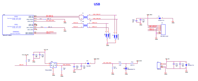
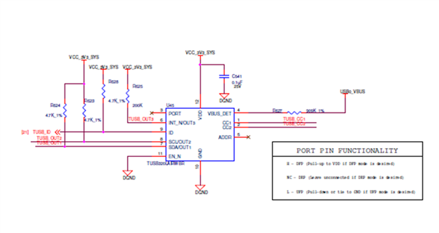
The Schematic image is attached below for your reference.

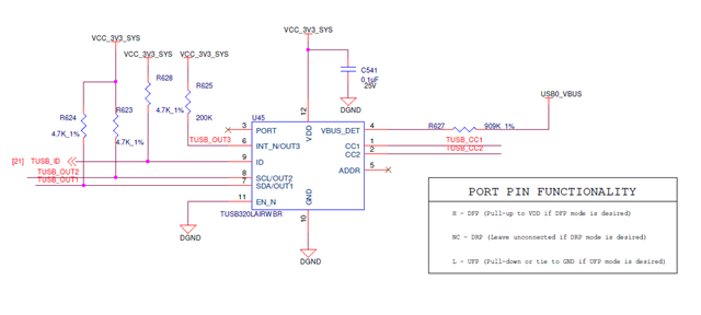
Please advise us, why the ID pin stays idle(high) even with external DFP(host) connectivity?

  • Hi Dharani,

    For the ID pin, we recommend a 200KOhm pull-up, as a weaker pull-up will ensure that the ID pin pulls down properly.

    When connected to a DFP, the TUSB320 will configure as a UFP. The ID pin is not used when the TUSB320 configures as a UFP, and is only used when the TUSB320 configures as a DFP. 

    Can you monitor the CC pins when you expect the ID pin to be low, to ensure the CC lines are connecting as expected? You can also try forcing the PORT pin to DFP mode to ensure it configures as intended.

    Thanks,

    Ryan

  • Hi Ryan,

    Thanks for the clarification regarding UFP and DFP mode of TUSB320.

    We have changed the ID pin pullup value to 200k and configured the TUSB320 to DFP Mode by forcing the port pin (Pulled to VDD).

    But still, the ID pin stays high.

    ​Please suggest, how to proceed further?

    ​Thanks & Regards,

    Dharani. T

  • Hi Dharani,

    Is it possible to monitor the CC pins before and after a connection is made when in I2C mode? If the device is set to DFP mode, the CC pins should be pulled-up when there is nothing connected, and then pulled down to the specified voltage below for default current-advertisement:

    Thanks,

    Ryan

  • Hi Ryan,

    Thanks for the suggestion.

    1. Sure, we will monitor the CC pins.

    2. We are not using I2C in our design.

    Is it mandatory to use I2C, if are using the TUSB320 in DRP Mode?

    Thanks & Regards,

    Dharani. T

  • Hi Dharani,

    2. We are not using I2C in our design.

    Is it mandatory to use I2C, if are using the TUSB320 in DRP Mode?

    No, it is not mandatory.

    Is it possible to monitor the CC pins before and after a connection is made when in I2C mode?

    I misspoke here. I meant DFP mode, not I2C mode. 

    Thanks,

    Ryan

  • Hi Ryan,

    We have monitored the CC1,CC2  pin voltage in different use case.

    Please look into the below table for the observations:

    TUSB320LAI External Device VBUS VBUS_Detect CC1 CC2 ID Remarks
    DRP Not Connected 0 0 0 0 3.3 We are having a load switch on our design which provides 5V for VBUS during DFP Mode.
    This load switch is enabled based on ID pin of CC controller (Enabled, If ID is low)
    Not  Connected  Laptop (A-C Cable)
    A type connected to laptop. Probed on C type pins
    5 - 5 0 - Vice Versa of CC Pin values. If the cable orientation is flipped
    Not  Connected  Laptop (C-C Cable) 0 - 0-3.3V (Square wave with a period of 75ms)   - Vice Versa of CC Pin values. If the cable orientation is flipped
    DRP
    (Expected to be DFP)
    Thumbdrive
    (Expected to be UFP)
    0 0 0 0 3.3  
    DRP
    (Expected to be UFP)
    Laptop (A-C Cable)
    A type connected to laptop. Probed on C type pins
    (Expected to be DFP)
    5 0.481 5 5 3.3  
    DRP
    (Expected to be UFP)
    Laptop (C-C Cable)
    (Expected to be DFP)
    0 0 0-3.3V (Square wave with a period of 75ms) 0-3.3V (Square wave with a period of 75ms) 3.3  
    DRP
    (Expected to be UFP)
    Wall Adapter (C type output)
    (Expected to be DFP)
    5 0.481 5 5 3.3  

    I am attaching the CC controller schematics section along with load switch for your reference.

    Please check and advice us

    Thanks & Regards,

    Dharani. T

  • Hi Ryan,

    One more  query,

    Will TUSB320 switch its mode based on external connectivity?

    or 

    Do we need to configure the mode of TUSB320 (either using port pin or through I2C communication)?

    In our design, we are not using neither port pin nor I2C pins.

    Thanks & Regards,

    Dharani. T

  • Hi Dharani,

    TUSB320LAI External Device VBUS VBUS_Detect CC1 CC2 ID Remarks
    DRP Not Connected 0 0 0 0 3.3 We are having a load switch on our design which provides 5V for VBUS during DFP Mode.
    This load switch is enabled based on ID pin of CC controller (Enabled, If ID is low)

    For this scenario, the TUSB320 is powered and enabled, correct? In a DRP configuration, the CC pins should be continually toggling between high and low when there is no connection. If there is no toggling on the CC lanes, then it seems like the TUSB320 is either not powered or enabling correctly, or is not being set to DRP mode for some reason.

    Not  Connected  Laptop (A-C Cable)
    A type connected to laptop. Probed on C type pins
    5 - 5 0 - Vice Versa of CC Pin values. If the cable orientation is flipped
    Not  Connected  Laptop (C-C Cable) 0 - 0-3.3V (Square wave with a period of 75ms)   -

    Vice Versa of CC Pin values. If the cable orientation is flipped

    These values make sense. Legacy cables (A to C) are set with the A side of the cable acting as host, so the type-C pins should be pulled up to reflect that. CC lines toggling indicate that the laptop is also set to act as a DRP, which also makes sense.

    DRP
    (Expected to be DFP)
    Thumbdrive
    (Expected to be UFP)
    0 0 0 0

    3.3

    Is it possible to set the TUSB320 explicitly as a DFP and see if that improves performance? CC pin voltages are indicating there is no connection being made, as the CC pins typically have some level of voltage on them in a successful connection. Again, please ensure the TUSB320 is powered correctly, and that the CC pins are toggling as expected before a connection.

    DRP
    (Expected to be UFP)
    Laptop (A-C Cable)
    A type connected to laptop. Probed on C type pins
    (Expected to be DFP)
    5 0.481 5 5 3.3  
    DRP
    (Expected to be UFP)
    Laptop (C-C Cable)
    (Expected to be DFP)
    0 0 0-3.3V (Square wave with a period of 75ms) 0-3.3V (Square wave with a period of 75ms) 3.3  
    DRP
    (Expected to be UFP)
    Wall Adapter (C type output)
    (Expected to be DFP)
    5 0.481 5 5 3.3

    Both the CC pins being 5V would indicate here that the laptop is connecting as expected, however there are not seeing any connection or pull-down resistance that the TUSB320 should be providing. This is especially odd because even if there is no power being provided to the TUSB320, there should at least be a pull-down voltage on the CC pins, causing a DFP device to be able to connect to the TUSB320.

    One recommendation I have, looking at the CC pins, would be to remove the CMC choke and ESD diodes from the path of the CC pins, and directly connecting the CC pins of the type-C connector to the TUSB320. Also, what is the clamping voltage of these ESD diodes? Typically, we recommend directly connecting the CC pins of the controller to the connector, with no components between.

    Will TUSB320 switch its mode based on external connectivity?

    or 

    Do we need to configure the mode of TUSB320 (either using port pin or through I2C communication)?

    The TUSB320 will change it's mode when set as a DRP based on the detected pull-up or pull-down resistors on the opposite side of the cable.

    Thanks,

    Ryan

  • Hi Ryan,

    Thanks for the timely reply.

    Sure, We will bypass the CMC & isolate ESD on CC lines & we will monitor the CC Lines.

    We will also update you on the signal behavior on the DFP Mode.

    The clamping voltage of ESD diode is 6.4V(with IPP - 1A) & 8.4V(with IPP - 5A)

    Is there concern regarding this clamping voltage?

    Thanks & Regards,

    Dharani. T

  • Hi Ryan,

    Thanks for your constant support.
    After bypassing CMC & isolating the ESD on CC lines.
    We observed the below things on the CC Lines& ID pins toggles based on external connectivity.

    TUSB320 External Device VBUS VBUS_Detect CC1 CC2 ID Remarks
    DRP Not Connected 0 0 0-3.3V (Square wave with a period of 75ms) 0-3.3V (Square wave with a period of 75ms) 3.3 We are having a load switch on our design which provides 5V for VBUS during DFP Mode.
    This load switch is enabled based on ID pin of CC controller (Enabled, If ID is low)
    DRP
    (DFP)
    Thumbdrive
    (UFP)
    0 0 1.6 0 0 We are having a load switch on our design which provides 5V for VBUS during DFP Mode.
    This load switch is enabled based on ID pin of CC controller (Enabled, If ID is low)
    Vice Versa of CC Pin values. If the cable orientation is flipped

    Thanks & Regards,

    Dharani. T

  • Hi Dharani,

    This behavior is much more in line with how we would expect the signal to work over the CC lines. Are you seeing a connection able to be made now over the type-C port? 

    Thanks,

    Ryan