Part Number: TIC12400-Q1
Other Parts Discussed in Thread: TIC12400
Tool/software:
Hello,
I have a board with TIC12400-Q1 and esp32-wroom
The schematic:
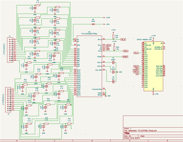
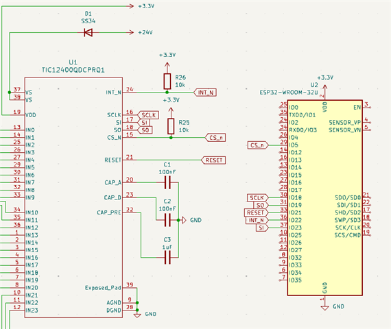
Like datasheet, i have pull-up's in /INT and CS_n
24V in VS and 3.3v in VDD
So, i make a simple script in micropython, try to read the device ID:
from machine import Pin, SPI
import time
PIN_CS = 5
PIN_RESET = 21
cs = Pin(PIN_CS, Pin.OUT, value=1) #starts with CS_N HIGH
reset = Pin(PIN_RESET, Pin.OUT, value=0) #starts with reset LOW
spi = SPI(2,baudrate=100_000, polarity=0, phase=1, bits=8, firstbit=SPI.MSB, sck=Pin(18), mosi=Pin(23), miso=Pin(19))
print("Init TIC")
time.sleep_ms(15) #15ms before reset
reset.value(1) # put RESET in HIGH before transmit
time.sleep_ms(1) # wait 6ms before starts transmission
# read decive ID
tx = bytearray([0x02, 0x00, 0x00, 0x00]) #32bit with 0x01 add
rx = bytearray(4)
cs.value(0) #put CS_n in LOW, to start transmission
time.sleep_ms(1) #waits 1ms before start transmission
spi.write_readinto(tx, rx) #start transmission
time.sleep_us(1) #wait 1ms before ends transmission
cs.value(1) # put CS_n in HIGH to end transmission
# show RX
device_id = (rx[1] << 8) | rx[2] #collect data from reply RX MOSI
print("TX =", ["0x%02X" % b for b in tx]) #show TX data
print("RX =", ["0x%02X" % b for b in rx]) #show RX data
print("Device ID = 0x%04X" % device_id) #show DEVICE ID
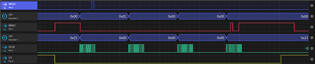
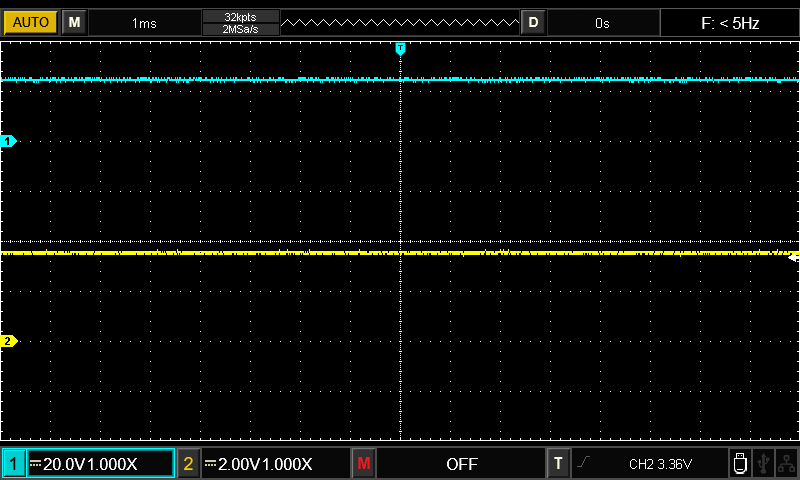
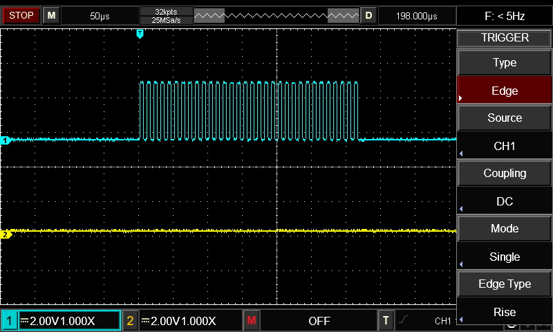
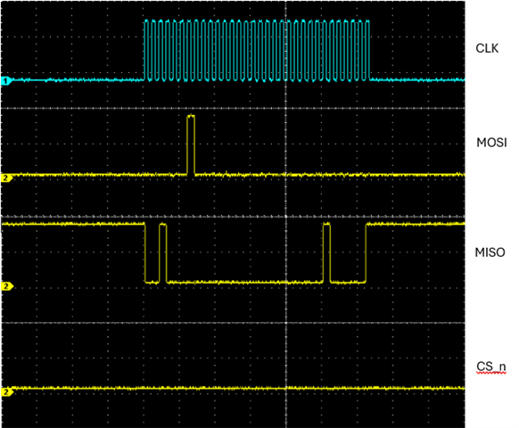
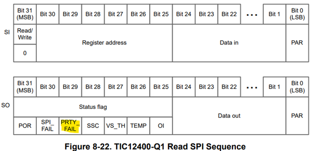
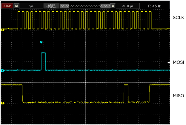
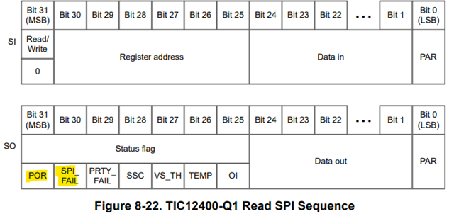
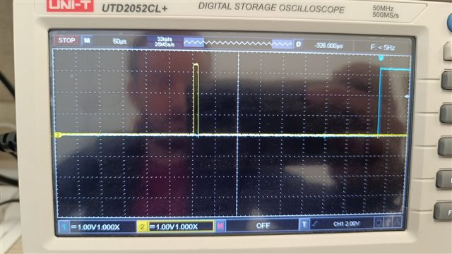
In osciloscope, I have this signals:
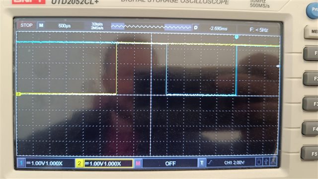
blue: CS_n
yellow: RESET
-----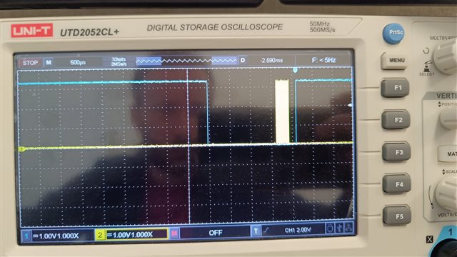
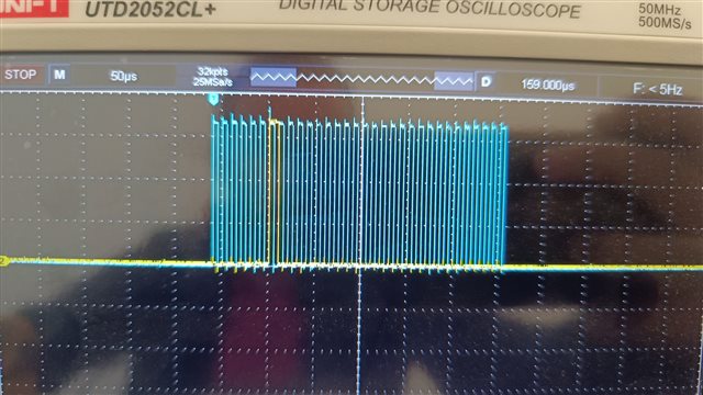
blue: CS_n
yellow: SCLK
-------
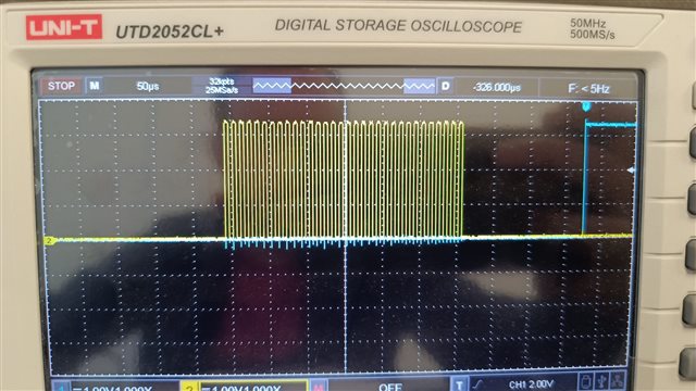
blue: CS_n
yellow: MISO (SO)
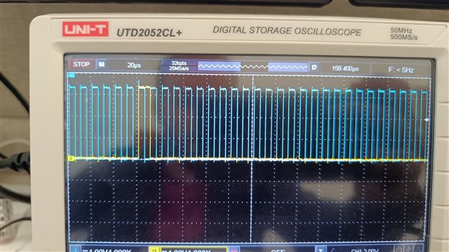
blue: SLCK
yellow: MISO (SO)
The MOSI pin never chages the state, is allways in LOW. Allways LOW in osciloscope.
I already try 3 different boards with new TIC12400, and is the same behaviour in all.
Is possible to have some support? The design is good, and the code is allright?