


Part Number: TSER9615
Other Parts Discussed in Thread: TDES9640, , TSER953, TPD1E0B04, TPD1E01B04
Tool/software:
Dear Support,
we have a few question regarding using TSER9615 ( 7.5G) and TSER953 ( 4G) connected to TDES9640 via STP ( no power over TP data)
TSER953
1a) When TSER953 connected via STP synchronous mode needs to use AC caps anything between 33nF to 100nF on P/N signal is that correct?
1b) Is there any drawback to use 100nF?
2a) When TSER953 connected via STP non- synchronous mode needs to use AC caps 100nF on P/N signal is that correct?
2b) Only 100nF will work?
3a) V3 link (4G) output voltage is 1.21V, can you please propose unidirectional ESD diode for P and N signals to GND? TPD1E01B04 or TPD1E0B04
3b) From your experience is it better to place the ESD diode between SER and AC caps or AC caps and cable?
3c) Do you recommend bidirectional ESD or unidirectional ESD between P and GND, N and GND?
3d) Do you recommend bidirectional ESD between P and N signal ?
4a) Do you have a selection guide for the CMC TSER953 ( 4G)? What a re the critical parameters?
5a) Do you have a selection for the STP cable and STP connector for TSER953 (4G)? What are the critical parameters?
TSER9615
6a) When TSER9615 connected via STP synchronous mode what AC caps are needed it is not stated in datasheet?
6b) Can TSER9615 working STP synchronous mode?
7a) When TSER9615 connected via STP non- synchronous mode needs to use AC caps 100nF on P/N signal is that correct?
7b) Only 100nF will work?
8a) V3 link (7.5G) output voltage is 1.21V, can you please propose unidirectional ESD diode for P and N signals to GND? TPD1E01B04 or TPD1E0B04
8b) From your experience is it better to place the ESD diode between SER and AC caps or AC caps and cable?
8c) Do you recommend bidirectional ESD or unidirectional ESD between P and GND, N and GND?
8d) Do you recommend bidirectional ESD between P and N signal ?
9a) Do you have a selection guide for the CMC TSER9615 ( 7.5G)? What a re the critical parameters?
10a) Do you have a selection for the STP cable and STP connector for TSER9615 (7.5G)? What are the critical parameters?
TSER9615 and TSER953
11) Regarding the line fault network , the RLF resistor should be on DESER side or on SER side? referring to SNLA322 has this resistor on DSER side (24k9) while the datasheet has it on SER side (10k)
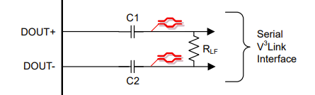
12) please can you tell the STP line-fault network example from SNLA322 ( page39) is ok to use for when only data through STP no power ( power is separate)? for booth devices
Applicable Thresholds • Normal Cable • Open Cable • "+" to "-" Short • "+" Short to Ground • "-" Short to Ground • Short to Battery
13) Only gpio0 and 1 can be used for this ? Because only this pins have ADC?
14) the network should be implemented after cable before the ESD/CMC and AC caps?
15a) the the EVB HSDC089B there are different values used for the network than SNLA322 , which one is correct?
15b) on the SNLA322 the GPIO pins have some protection diodes to 1.1V while on the HSDC089B this is missing, are the diodes required? We assume these are the protection didoes for GPIO
15c) the 1.1V we can use the VDD_1P1_D or VDD_1P1_DRV or VDD_1P1_PLL or external 1V1 rail?
15d) is the 1.1V because of the ADC on GPIO?
Best Regards,
d.
