Part Number: DP83867IS
Other Parts Discussed in Thread: DP83867E
Tool/software:
HI Team,
We have introduced the part DP83867ISRGZ on our design to have "100base ethernet" output from the device to provide internet to external device. On our existing device we have GSM modem EG25G ( which has SGMII interface for ethernet ).
So we opted DP83867IS since it has SGMII interface, We completed our design and reviewed it by TI team on below forum
Currently we have assembled PCB on our hand and while we are testing the ethernet is not wokring. Could you please review and confirm wherther anything we missed on hardware design regarding SGMII interface?
Attached particulate schematic part in this loop, SNM476_V1P1_20250627_TI_Eth.pdf
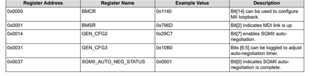
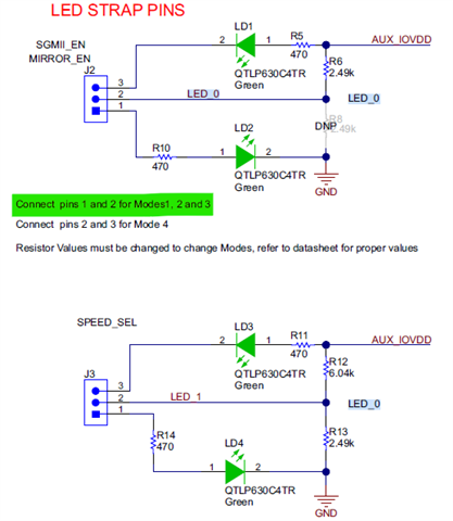
Specifically, Do we need to maintain any particular state on LED_0 ( pin# 47 ) & LED_1 ( pin# 46 ) pins on DP83867ISRGZ IC? to successfully enable SGMII interface?
Its crucial for us to release this hardware to production immediately, So prompt response for this query will be appreciated. Kindly do the needful.
Also our team ( Trimble ) is sitting in Chennai, Tamilnadu, India. So it will be helpful is any FAE in india assist us directly to mitigate this issue.