TMDS442: TMDS442:For unconnected HDMI input channels

Part Number: TMDS442


Tool/software:

Hello Team,

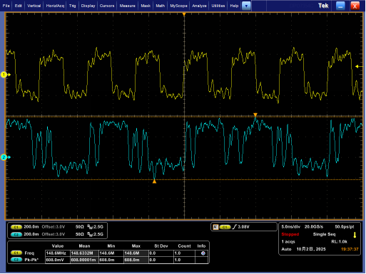
I have a question about the operation of this IC when an HDMI signal is input to the CH1 input and no HDMI input signal is input to the CH2 input.

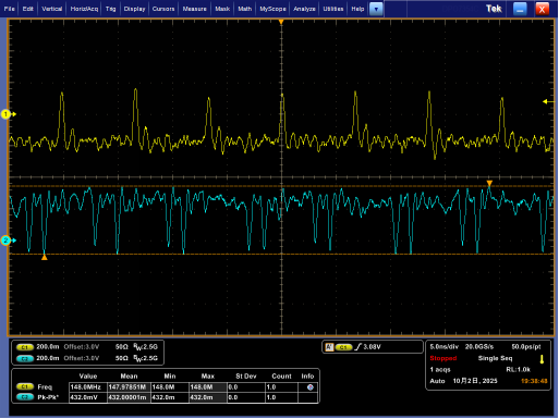
If CH2 is selected at this time, there is a chip that outputs a degraded CH1 input waveform to the HDMI output.

It appears that this phenomenon may occur in adjacent CHs.

Depending on the monitor, this signal may cause a degraded image of the adjacent CH to be displayed, even though the CH that originally has no HDMI input is selected.

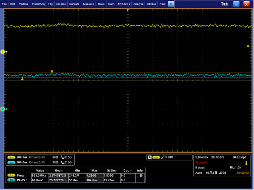
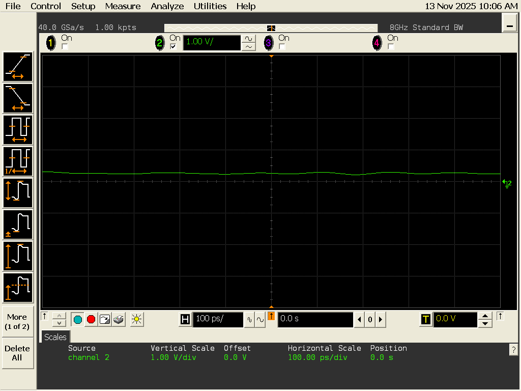
As far as we can check the waveform from outside the IC, we cannot see any signal on the TMDS pin on the input side, so we believe that the phenomenon is occurring inside the chip.

Is there any countermeasure for this phenomenon?

Thank you,

Tomohiro

  • Hello Team,

    Additional information is provided.

    Since no HDMI signal is input, 5V_PWR is Low.
    Under the conditions described in the following table in the datasheet, the area circled in red is applicable.

    The TMDS output (Y/Z) is in a high impedance state, so it seems to be leaking from the unselected input CH to the output side.

    I hope this is helpful.

    Thank you,

    Tomohiro

  • Tomohiro-san

    An unused input channel can be externally biased to prevent output oscillation. The complementary input pin is recommended to be grounded through a 1-kΩ resistor and the other pin left open. If they do this, then are you still seeing degraded CH1 input waveform at the HDMI output?

    Thanks

    David

  • Hi David,

    Thank you for your reply.

    However, the CH without an HDMI input is not always unused; depending on the situation, an HDMI signal may or may not be connected.

    The method you suggested could potentially affect the HDMI signal.
    Is there another way?

    Also, I attached a table for 5V_PWR_STATUS in the previous post.
    However, there was a discrepancy between this table and the actual settings.

    The table states I2CEN = High, but the actual setting was I2CEN = Low.

    When I2CEN = Low, how does the Y/Z output function?

    For reference, when _OE is set High, the signal leaking into output CH disappears.
    So it appears that the Y/Z outputs are not high impedance when I2CEN = Low.

    Thank you,

    Tomohiro

  • Tomohiro-san

    The I2C driver at sink side, SCL_SINK and SDA_SINK, are enabled by setting I2CEN high. When I2CEN is low, the I2C driver can not forward a low state to the I2C bus connected at the sink port. The I2C driver of each source port, SCL and SDA, is also controlled by its 5V_PWR signal. A valid 5-V signal appearing at the input of 5V_PWR enables the I2C driver of the source port. So in the table, with 5V_PWR1 being low, the I2C driver of the source is disabled and Y/Z is High-Z.

    Can they add the 1Mohm resistor to GND on the complementary input pin? The 1M is a weak resistor so the impact to HDMI signal is minimal.

    Thanks

    David

  • Hi David,
    Understood. I'll try adding a 1MΩ resistor between the P side of the complementary input pin and GND.
    Also, thank you for your response regarding the I2C driver and Y/Z output.
    However, it appears the Y/Z output behavior differs when the I2C driver is disabled and when _OE is high.
    Why is this?
    (Since the datasheet states both are high impedance, I assumed they would behave identically.)
    I will post the relevant waveforms below.
     Wave 1(Normal output): HDMI input = ON, I2C_EN = Low, 5V_PWR = High, _OE = Low
        Ch1 = HDMI_TMDS_CLK_P
        Ch2 = HDMI_TMDS_D2_P
     Wave 2(Leakage output): HDMI input = OFF, I2C_EN = Low, 5V_PWR = Low, _OE = Low
        Ch1 = HDMI_TMDS_CLK_P
        Ch2 = HDMI_TMDS_D2_P
     Wave 3(Output stop): HDMI input = OFF, I2C_EN = Low, 5V_PWR = Low, _OE = High
        Ch1 = HDMI_TMDS_CLK_P
        Ch2 = HDMI_TMDS_D2_P

    Thank you,

    Tomohiro

  • Hi David,

    I added a 1MΩ resistor between the P side of the complementary input pin and GND, but there was no change in the output waveform.
    Are there any other possible countermeasures?

    As a note, even for channels with an HDMI input connected, if the monitor is set to turn off when the PC enters sleep mode or after a period of inactivity, the HDMI input signal will stop, and similarly degraded input waveforms will be output.
    This is a common setting, so I'm extremely troubled that this issue is occurring.

    Please continue to cooperate.

    Thank you,

    Tomohiro

  • Tomohiro-san

    Under this condition, Wave 2(Leakage output): HDMI input = OFF, I2C_EN = Low, 5V_PWR = Low, _OE = Low, if you put a 1k or 1M pulldown on the negative of the input channel, do you still see the leaded waveform?

    Thanks

    David

  • Hi David,

    Under the conditions of HDMI input = OFF, I2C_EN = Low, 5V_PWR = Low, and _OE = Low, a leakage waveform is still observed even when a 1MΩ pull-down resistor is connected to the negative side of the input channel.

    The waveforms shown below demonstrate the case with and without a 1MΩ pull-down resistor connected.

    Wave1(without a 1MΩ)

    Wave2(with a 1MΩ)

    Adding 1MΩ will change the positive offset of the output waveform. Could this be a clue to the cause?
    I apologize, but could you please tell me other ways to improve it?

    One more thing—I'd like answers regarding the following points:
    ・The behavior of the Y/Z output differs between when the I2C driver is disabled and when _OE is high.
     (Why doesn't the output become high impedance when I2C_EN = Low, 5V_PWR = Low, and _OE = Low?)

    Thank you,

    Tomohiro

  • Tomohiro-san

    Can you please use a 1kohm resistor at the negative input? My expectation is that it should fix this issue. If not, we may need to take a look at the board to see if there is another source of crosstalk,

    Thanks

    David

  • Hi David,

    Using a 1kΩ resistor in the negative input eliminated the phenomenon.
    Thank you so much for your help!

    I apologize for the inconvenience, but could you also provide answers to the questions I sent in my previous post?

    Thank you,

    Tomohiro

  • Tomohiro-san

    The I2C_EN controls the sink port DDC I2C output while OE controls the sink port TMDS output (Y/Z). 

    When OE is high, the output is disabled and shows up as a high Z state. 

    When OE is low, the output is enabled and reflects the input (A/B) condition. In this case, the input is floating. But the TMDS442 input is not a failsafe I/O so if the output is still enabled, you will see output oscillation. I was hoping using a 1M to GND on the unused input would properly biased it to stop the output oscillation, but it looks like you have to use 1k to properly biased the unused input and this aligns with the description in the TMDS442 datasheet. 

    You can also drive OE pin high when there is no input so the output will not reflect this oscillation condition.

    Thanks

    David

  • Hi David,

    I'm sorry, but it seems we're not on the same page regarding what I'd like to ask.
    I am reattaching the table from the data sheet I previously sent and sending you new questions.

    As indicated in the red box, is it correct that when 5V_PWR goes low, Y/Z becomes high impedance?

    If this is correct, why do the waveforms differ under the following two conditions?

    Wave 2(Leakage output): HDMI input = OFF, I2C_EN = Low, 5V_PWR = Low, _OE = Low
    Wave 3(Output stop): HDMI input = OFF, I2C_EN = Low, 5V_PWR = Low, _OE = High

    (Since only the High/Low states of the OE pin differ, both should be high impedance if the datasheet is correct.)

    Could you also answer the following additional questions?

    1.Will a pull-down resistor of 1kΩ affect the HDMI signal characteristics?

    2.What is the recommended range for pull-down resistors?

    Thank you,

    Tomohiro

  • Tomohiro-san

    Is this the 5V_PWR of the unused input being hold low? 

    The HDMI have 50ohm termination to 3.3V, which is a stronger pullup, so I don't believe the 1K will significantly affect the HDMI signal characteristic. But if it is possible, you can also control the OE pin, drive it high when there is no input, and drive it low when there is a valid input. 

    There is also no recommended range for the pull-down resistors. You have to use 1k pulldown resistors.

    Thanks

    David

  • Hi David,

    Thank you for answering the two questions.
    I understand.

    Yes, the unused input 5V_PWR is held at a low level.

    Are there other reasons why it doesn't become high impedance?

    Thank you,

    Tomohiro

  • Tomohiro-san

    Thanks for the confirmation. I do agree with you that the 5V_PWR behavior does not match with the output behavior as defined by the table. 

    The TMDS442 is a pretty old device and I currently do not have a EVM to check out this behavior. Please give me couple days and let me see if I can find one in the lab to duplicate this condition.

    Thanks

    David

  • Hi David,

    Thank you for the suggestion.

    I don't mind if it takes a while, so it would be helpful if you could investigate.

    Thank you,

    Tomohiro

  • Tomohiro-san

    I understand, and will provide an update once I locate a TMDS442 EVM in my lab.

    Thanks

    David

  • Tomohiro-san

    I am not able to find a TMDS442 EVM in the lab to duplicate what you find. Any chance you can send me your board so I can look at it in my lab?

    Thanks

    David

  • Hi David,

    I can send you my board.
    The board by itself will not be powered, so I will send it to you in the form of a prototype.
    You can access the TMDS442 by removing the screws and opening the top cover of the enclosure.

    Could you please provide us with information on where to send it?

    Thank you,

    Tomohiro

  • Tomohiro-san

    Can you please accept my friendship request so I can send you my mailing address? 

    Can you also provide instruction on how to power up the board?

    Thanks

    David

  • Hi David,

    I have accepted your friendship request.

    I will send you the board power-up procedure via private message.

    Thank you,

    Tomohiro

  • Tomohiro-san

    Thank you. I provide you my physical mailing address in the private message.

    David