DP83867CS:Subject: Inquiry Regarding RJ45 with Integrated Transformer

Part Number: DP83867CS

Tool/software:

Hello, 

I have a question regarding the specifications of RJ45 connectors with integrated transformers for use with the DP83867CSRGZT, specifically concerning the center tap connection method.
We are considering the following two RJ45 connector options:
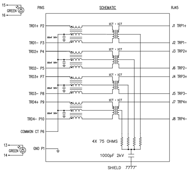
①SI-51005-F
- The center taps are shared, and each has a built-in 22nF capacitor. (Pin P6: COMMON CT)
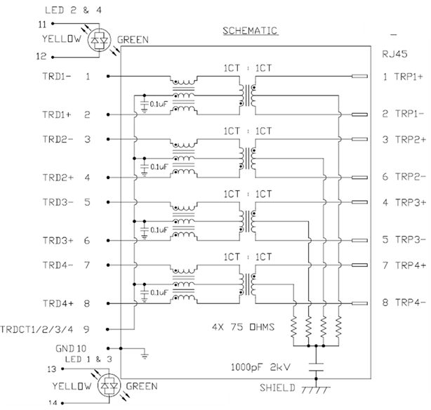
②0879-2C2R-V4
- The center taps are shared, and each has a built-in 0.1nF capacitor. (Pin 9: TRDCT1/2/3/4)

We would appreciate your confirmation and response regarding the following points:

(1) Regarding the center tap pin handling of options ① and ②, since they are internally connected to capacitors, is it correct to assume that no external capacitor or GND connection is necessary?
※ In the evaluation board (schematic publicly available) using [DP83867CSRGZT] and [0879-2C2R-V], Pin 9 (TRDCT1/2/3/4) was left NC (not connected).


(2) The internal capacitor values differ between ① and ②.
 The DP83867 datasheet recommends connecting a “0.1μF” capacitor to the center tap.
 Does this mean that option ① is not recommended?

(3) If option ① is not recommended, but we still wish to use it, what kind of processing, considerations, or evaluations would be necessary?

Thank you very much for your support.

Best regards,

takuya.tokuo

  • Takuya-san

    Please see my inserted response below.

    (1) Regarding the center tap pin handling of options ① and ②, since they are internally connected to capacitors, is it correct to assume that no external capacitor or GND connection is necessary?
    ※ In the evaluation board (schematic publicly available) using [DP83867CSRGZT] and [0879-2C2R-V], Pin 9 (TRDCT1/2/3/4) was left NC (not connected).

    Correct, no external capacitor or GND connection is needed.

    (2) The internal capacitor values differ between ① and ②.
     The DP83867 datasheet recommends connecting a “0.1μF” capacitor to the center tap.
     Does this mean that option ① is not recommended?

    (3) If option ① is not recommended, but we still wish to use it, what kind of processing, considerations, or evaluations would be necessary?

    Is it nF or uF? A 0.1µF capacitor is connected to the center tap of a transformer to provide common-mode filtering, which suppresses noise and stabilizes the voltage supply for a Ethernet Physical Layer (PHY) in a circuit. We have always used 0.1uF transformer in our design and have not characterized a transformer with 0.22uF center tap capacitor so its performance can not be guaranteed. 

    Also, please make sure other spec of transformer is met as shown below. 

    Thanks

    David

  • Hi David-san,

    Thank you for your reply.

    >>Is it nF or uF?

    The correct capacitance value for 0879-2C2R-V4 is 0.1 µF.
    We apologize for the error in the previous documentation.


    Also, thank you very much for sharing the specifications of the transformer. We will review them accordingly.


    Best regards,
    takuya.tokuo

  • Hi David-san,

    I'm sorry, I have one more question.


    In the datasheet for the DP83867, it states the following:
    "Each center tap on the side connected to the PHY must be isolated from each other and connected to ground through a decoupling capacitor (0.1μF recommended)."

    The RJ45 connectors I intend to use both have internally shorted center taps. However, since each channel has capacitors connected internally, I believe this type of component should be acceptable to use.
    Is this understanding correct?

    Based on what I’ve read in several forums, RJ45 connectors with shorted center taps and no internal capacitors are generally considered not suitable.
    As for those with internal capacitors, they seem to be acceptable, but I’d like to confirm—is my understanding correct?

    Best regards,
    takuya.tokuo

  • Takuya-san

    Your understanding is correct. Below is an example of an integrated RJ45 with center tap shorted together.

    Thanks

    David

  • Hi David-san,

    Thank you for your reply.

    I have one last question.

    The aforementioned "①SI-51005-F" does not meet the following two recommended requirements.

    If we use this component as is, what kind of risks should we be aware of for each of the following?

    (1) The internal capacitor's capacitance is 22nF (0.022㎌), which is different from the recommended capacitance (0.1㎌).
    (2) Some of the transformer specifications you provided do not meet these requirements.
    *Insertion loss and crosstalk

    Best regards,

    takuya.tokuo

  • Takuya-san

    A 0.1µF capacitor is connected to the center tap of a transformer to provide common-mode filtering, which suppresses noise and stabilizes the voltage supply for a Ethernet Physical Layer (PHY) in a circuit. If using a 0.022uF capacitor, common-mode filtering may get degraded.

    Insertion loss and crosstalk impact the Ethernet signal quality, so you may have link up issue, or if linked up, you may have packet drop issue due to signal integrity degradation.

    Thanks

    David

  • Hi David-san,

    Thank you for your response.


    I’ve understood the details of the risks.
    Thank you for the valuable information.


    I will use this as a reference for selecting RJ45 components.


    That will be all for my questions.
    Thank you very much.
    Much appreciated.

    Best regards,

    takuya.tokuo