TUSB1042I: Having trouble connecting camera to PC

Part Number: TUSB1042I
Other Parts Discussed in Thread: TUSB1042EVM

Tool/software:

Hi, I'm using the linear redriver/MUX to send a USB3.1 camera signal to a PC. I have USB-C on both ends. The PC is on the SSRX/TX side and we know we will only be able to detect orientation in one direction on the PC side. We can fix that problem with another MUX or a different part, but for now we are just trying to get camera feed. We can get the camera to enumerate and show up briefly but it either drops immediately or after a few frames. The input on the camera side also goes through a MUX on an external board, same part, TUSB1042. I have 100nF capacitors on the TX traces on both sides. Do I need to change the capacitor value? I am in control of the external board and can change those capacitor values if I need to. I also made a layout error and the capacitors on the SSRX/TX side are far from the chip and close to the connector going out. I can rework that to see if it improves the signal.

External board: USB3.1 Camera -->  USB3 connector --> TUSB1042 --> USB-C connector

Board in question: USB-C connector --> TUSB1042 --> USB-C --> PC

  • Hi,

    Are you able to share a block diagram/ schematic of your system?

    Was a CC controller used here?

    we know we will only be able to detect orientation in one direction on the PC side. We can fix that problem with another MUX or a different part, but for now we are just trying to get camera feed.

    The TUSB1042 is an active mux, so we should be able to work in both orientations without another MUX here.

    We can get the camera to enumerate and show up briefly but it either drops immediately or after a few frames.

    This looks to be an EQ issue. The link probably finished enumeration by seeing the appropriate terminations, but the signa quality itself is poor, so the link drops. What is the EQ value used currently?

    I have 100nF capacitors on the TX traces on both sides. Do I need to change the capacitor value?

    Is the board using a receptacle or plug as the connection to the PC?

    If you can provide design files for the board I will be help by completing a schematic and layout review to make sure our part is implemented correctly. If possible are you able to test with a TUSB1042EVM?

  • Was a CC controller used here?

    We are connecting CC pins to a comparator and using a microcontroller on the board (not represented on the schematic posted by labeled "SWITCH_SELECT") to toggle the flip pin.

    What is the EQ value used currently?

    We have tried the full range of resistor settings for EQ.

    Is the board using a receptacle or plug as the connection to the PC?

    We are using receptacle for both sides.

    Schematic is attached. Thank you!

    3582.USB.pdf

  • Hi,

    Thanks for the schematic. 

    I will have a full review ready in 1 day, but from a look at the schematic I have a few comments.

    The TUSB1042 is an active mux, so we should be able to work in both orientations without another MUX here.

    As this is a receptacle to receptacle system, you will need another MUX you function. Your initial statement is correct

    We are connecting CC pins to a comparator and using a microcontroller on the board (not represented on the schematic posted by labeled "SWITCH_SELECT") to toggle the flip pin.

    This seems like it should work, and we do see enumeration begin, so most likely this is fine.

    This design looks similar to the application of the TUSB1042-EVM. Are you able to test with our EVM here?

    We have tried the full range of resistor settings for EQ.

    Are you able to send an eye diagram for the output waveforms at EQ setting 0, 8, and 15?

  • Thank you for the reply. Yes, we do have TUSB1042-EVM in house. 

    We do not have a fast enough scope for an eye diagram.

  • Ok gotcha,

    Could you try with the EVM to see if you get the same results?

    What's the BW of the scope you have access to?

  • Hi,

    Is there a CC controller on the camera side USB Type-C connector? How is Vbus supplied here?

    Can you share the full schematic of the board. Id like a full view of the system to debug. The AC coupling and routing looks fine here.

  • Is there a CC controller on the camera side USB Type-C connector?

    On the other side of J3, which is routed to the camera, there is a board in between with a PD controller used only for CC orientation. We are using STUSB4500 there with no CC pull up or down, it is handled by the controller.

    How is Vbus supplied here?

    VBUS (at TP3) is supplied by a voltage regulator that is turned on and off through FETs by a microcontroller on the board.

    I'm sorry, I cannot share a full schematic at this time.

  • How is Vbus supplied here

    We do know VBUS at J3 works because we're able to send 15V to power our system on the other side which includes a 5V buck regulator for the camera.

  • Hi Megan,

    Is my understanding correct that there is only one CC controller present for the USB Type-C link connecting to the camera?

    Will the camera be using any form of DP alt, mode?

    Or will all video data be transmitted over USB signaling?

  • Can you share a block diagram of the end-to-end system with key components?

  • Yes, there is only one CC controller present on the camera link. It is intended to be all USB signaling. I will work on the block diagram.

  • Hi,

    We have tried the full range of resistor settings for EQ.

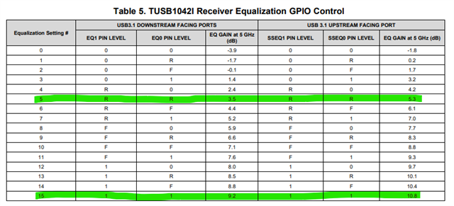
    There are 2 sets of EQ in the TUSB1042. We have the SSEQ0/1 (upstream), and EQ0/1 (downstream). Can you share what the values are currently when testing?

    Can you hare what the CC connections look like here? Are there PUPs on these pins?

  • Can you hare what the CC connections look like here? Are there PUPs on these pins?

    Both DFP_CC2 and CC1 have 10K pullups.

    Currently during testing, EQ settings are set this way:

    SSEQ0, SSEQ1, EQ_0, EQ_1 all tied to 3.3V through a zero ohm resistor.

  • Hi Megan,

    This level of equalization most likely too much for what the system needs. This could be the reason why the camera enumerates, but the USB data link fails.

    I understand you tested some different EQ configurations before, do you have any info of which ones?

    Were you able to test with the TUSB1042EVM? The EVM has jumpers on the GPIO control pins meaning we can cycle through the EQ settings without having to solder resistors. Testing with the EVM could give us a rough estimate for the EQ needed in your system, and we can tune accordingly.

  • I understand you tested some different EQ configurations before, do you have any info of which ones?

    I have tested SSEQ0, SSEQ1, EQ_0, EQ_1 all tied to GND through a 20k resistor. I have not tested any other settings that I have notes for. Soldering resistors is fine for me, the Eval board requires an uncommon cable we don't have.

  • Ok, so the only EQ settings we have tested are as follows. Is this correct?

    When tuning EQ, I recommend using the loss of the system to try to approximate the compensation needed. 

    Example)

    The pre-channel loss will be compensated by the SSEQ0/1, and the post-channel portion will be compensated by EQ0/1. We will need to tune these independently based off of the respective losses.

    Are you able to estimate the pre and post channel posses? 

    For PCB traces at 5Gbps the loss is approx. 0.5dB per inch.

  • Ok, so the only EQ settings we have tested are as follows. Is this correct?

    This is correct. Firmware engineer is testing the board with a new cable and having better camera feed results

    Are you able to estimate the pre and post channel posses? 

    For PCB traces at 5Gbps the loss is approx. 0.5dB per inch.

    Is this on the board only? These numbers are for PCB only.

    Prechannel ~1.1dB

    Post Channel ~.58dB

  • Hi,

    This is correct. Firmware engineer is testing the board with a new cable and having better camera feed results

    This imples the issue is with signal quality rather than routing. We should be able to tune this system.

    Is this on the board only? These numbers are for PCB only.

    Yes, this approximation is just for the board. 

    About how long are the cables used? Do we have an estimation of the loss of the cables?

    I would try the following settings based off of the losses provided. I will assume 3dB of loss per cable.

  • Hello,

    Closing thread due to inactivity. If you have any follow-up questions or concerns, feel free to reply.