Part Number: DP83869HM
Other Parts Discussed in Thread: DP83869, DP83869EVM
Tool/software:
I am having two issues with the Xilinx Versal Premium GEM 0 MAC connected to the TI DP83869HM PHY.
Issue 1: Can't ping the Ethernet interface from a Linux laptop.
Issue 2: PHY Loopback modes do not seem to work at either 100Mbps or 1Gbps speeds.
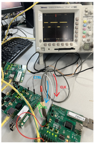
A mockup of the schematic is attached. The PHY is connected to magnetics and RJ45 connector via a board to board connector. The MAC PHY interface is RGMII.
Strapping settings for the PHY from the Excel 3324.DP83869_Schematic_Design_Review_Checklist.xlsx worksheet: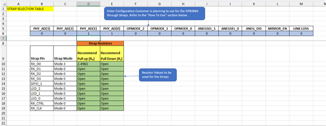
The MDIO interface does work and I have been able to dump PHY registers from the device. This register dump also shows the GEM0 MAC setup.
[0.016]****************************************
[0.049]Xilinx Versal Platform Loader and Manager
[0.083]Release 2023.2   Aug 13 2025  -  21:50:27
[0.119]Platform Version: v2.0 PMC: v2.0, PS: v2.0
[0.160]BOOTMODE: 0x0, MULTIBOOT: 0x0
[0.190]****************************************
[0.437]Non Secure Boot
[3.508]PLM Initialization Time
[3.536]***********Boot PDI Load: Started***********
[3.575]Loading PDI from SBI
[3.602]Monolithic/Master Device
[3.652]0.073 ms: PDI initialization time
[3.687]+++Loading Image#: 0x1, Name: SUB_SYSTEM_BOOT, Id: 0x18700000
[3.740]---Loading Partition#: 0x1, Id: 0x2
[330.352] 326.567 ms for Partition#: 0x1, Size: 357648 Bytes
[330.421]Enabled SSIT Interrupts
[330.452]+++Loading Image#: 0x2, Name: lpd, Id: 0x04210002
[330.502]---Loading Partition#: 0x2, Id: 0xC
[403.977] 73.427 ms for Partition#: 0x2, Size: 10384 Bytes
[409.080]---Loading Partition#: 0x3, Id: 0xB
[463.286] 50.233 ms for Partition#: 0x3, Size: 64160 Bytes
[465.799]+++Loading Image#: 0x3, Name: cpm, Id: 0x04218007
[470.790]---Loading Partition#: 0x4, Id: 0x14
[615.775] 140.925 ms for Partition#: 0x4, Size: 163008 Bytes
[618.289]+++Loading Image#: 0x4, Name: fpd, Id: 0x0420C003
[623.452]---Loading Partition#: 0x5, Id: 0x8
[627.863] 0.442 ms for Partition#: 0x5, Size: 4320 Bytes
[632.433]+++Loading Image#: 0x5, Name: CONFIG_MASTER, Id: 0x18700000
[638.460]---Loading Partition#: 0x6, Id: 0x13
[4334.165] 3691.643 ms for Partition#: 0x6, Size: 4034160 Bytes
[4336.963]***********Boot PDI Load: Done***********
[4341.510]4242.778 ms: ROM Time
[4344.350]Total PLM Boot Time


-----lwIP RAW Mode UDP Client Application-----
Read Options: = 0x000037F0
Write Options: = 0x000037F0
XEmacPs detect_phy: PHY detected at address 3.
link speed for phy address 3: 100
rxringptr: 0x00800660
txringptr: 0x008005F0
rx_bdspace: C00000
tx_bdspace: C10000
netif: added interface te IP addr 0.0.0.0 netmask 0.0.0.0 gw 0.0.0.0
netif: setting default interface te
Configuring default IP 192.168.0.10
Board IP:       192.168.0.10
Netmask :       255.255.255.0
Gateway :       192.168.0.1

udp_bind(ipaddr = 192.168.0.10, port = 5001)
udp_bind: bound to 192.168.0.10, port 5001)
udp_connect: connected to 192.168.0.10, port 5001)
---------------------------------------------------
 GEM 0 Statistics Registers After setup
 Xilinx setup of PHY and MAC should be complete
---------------------------------------------------
GEM Network Control               = 0x0000001C = 0000_0000_0000_0000_0000_0000_0001_1100
                                                 Bit 4 = 1 -> MDIO port enabled
												 Bit 3 = 1 -> TX Enabled
												 Bit 2 = 1 -> RX enabled
												 Bit 1 = 0 -> Loopback disabled
												 Bit 0 = 0 -> (Not defined in Xilinx documentation)
GEM Network Config                = 0x013F20C3 = 0000_0001_0011_1111_0010_0000_1100_0011
                                                 Bit 31 Reserved
												 Bit 30 = 0 -> Ignore IPG RX Er - disabled
												 Bit 29 = 0 -> Ignore NSP Change - RX bad Preamble - not setup
												 Bit 28 = 0 -> IPG stretch en - disabled
												 Bit 27 Reserved
												 Bit 26 = 0 -> Ignore RX FCS - disabled
												 Bit 25 = 0 -> En half Duplex RX - disabled
												 Bit 24 = 1 -> RX Chekcsum Offload enabled
												 Bit 23 = 0 -> Disable Copy of pause frames - disabled
												 Bit 22:21 = 01 -> 64 Bit AMBA (AHB/AXI)
												 Bit 20:18 = 111 -> MDC Clokc divisor - 224
												 Bit 17 = 1 -> FCS Remove - enabled so does not copy FCS to memory
												 Bit 16 = 1 -> Length field error frame discard - enabled
												 Bit 15:14 = 00 -> RX buffer Offset = 0
												 BIt 13 = 1 -> Pause enabled
												 Bit 12 = 0 -> Retry test - normal operation
												 Bit 11 Reserved
												 Bit 10 = 0 -> Gigabit mode enabled - disabled
												 Bit 9  = 0 -> External Address match enable - disabled
												 Bit 8  = 0 -> RX 1536 bytes frames - disabled
												 Bit 7  = 1 -> Unicast Hash enabled
												 Bit 6  = 1 -> Multicast hash enabled
												 Bit 5  = 0 -> No broadcast - disabled
												 Bit 4  = 0 -> Copy all frames - disabled
												 Bit 3  = 0 -> Jumbo frames - disabled
												 Bit 2  = 0 -> Discard Non-VLAN frames - disabled
												 Bit 1  = 1 -> Full Duplex enabled
												 Bit 0  = 1 -> Speed = 100Mb/s
GEM Network Status                = 0x00000006
GEM DMA Config                    = 0x40180F10
GEM TX Status                     = 0x00000000
GEM RX Q Pointer                  = 0x00C00000
GEM TX Q Pointer                  = 0x00C30000
GEM RX Status                     = 0x00000000
GEM APB Misc ISR                  = 0x00000000
GEM APB Misc IER                  = 0x00000000
GEM APB Misc IDR                  = 0x00000000
GEM APB Misc IMR                  = 0xFFFCF009
GEM PHY Manage                    = 0x5182A100
GEM Lockup Config                 = 0x07FFFFFF
GEM Revision                      = 0x0107010B
GEM TX Frame Octet L              = 0x00000000
GEM TX Frame Octet U              = 0x00000000
GEM TX Frame Count                = 0x00000000
GEM TX Frame Broadcast Count      = 0x00000000
GEM TX Frame Multicast Count      = 0x00000000
GEM TX Frame Pause Count          = 0x00000000
GEM TX Frame 64B Count            = 0x00000000
GEM TX Frame 65B Count            = 0x00000000
GEM TX Frame 128B Count           = 0x00000000
GEM TX Frame 256B Count           = 0x00000000
GEM TX Frame 512B Count           = 0x00000000
GEM TX Frame 1024B Count          = 0x00000000
GEM TX Frame 1518B Count          = 0x00000000
GEM TX Frame Underrun Count       = 0x00000000
GEM TX Single Collisions Count    = 0x00000000
GEM TX Multiple Collisions Count  = 0x00000000
GEM TX Excessive Collisions Count = 0x00000000
GEM TX Late Collisions Count      = 0x00000000
GEM TX Excessive Collisions Count = 0x00000000
GEM TX Deferred Frames Count      = 0x00000000
GEM TX Carrier Sense Error Count  = 0x00000000
GEM RX Octet Count L              = 0x00000000
GEM RX Octet Count U              = 0x00000000
GEM RX Frames Count               = 0x00000000
GEM RX Frames Broadcast Count     = 0x00000000
GEM RX Frames Multicast Count     = 0x00000000
GEM RX Frames Pause Count         = 0x00000000
GEM RX Frames 64B Count           = 0x00000000
GEM RX Frames 65B Count           = 0x00000000
GEM RX Frames 128B Count          = 0x00000000
GEM RX Frames 256B Count          = 0x00000000
GEM RX Frames 512B Count          = 0x00000000
GEM RX Frames 1024B Count         = 0x00000000
GEM RX Frames 1519B Count         = 0x00000000
GEM RX Frames Undersize Count     = 0x00000000
GEM RX Frames Oversize Count      = 0x00000000
GEM RX Jabber Count               = 0x00000000
GEM RX FCS Error Count            = 0x00000000
GEM RX Length Error Count         = 0x00000000
GEM RX Symbol Length Error Count  = 0x00000000
GEM RX Alignment Error Count      = 0x00000000
GEM RX Resource Error Count       = 0x00000000
GEM RX Overrun Error Count        = 0x00000000
GEM RX Header Error Count         = 0x00000000
GEM RX TCP Checksum Error Count   = 0x00000000
GEM RX UDP Checksum Error Count   = 0x00000000
GEM RX DMA Flush Count            = 0x0000001C

 --<{(| PHY Register dump |)}>--
PHY BMCR                       (0x0000) = 0x1140 = 0001_0001_0100_0000
                                                   Bit 15 = 0 -> Normal Operation (Not reset)
												   Bit 14 = 0 -> MII Loopback Enabled
												   Bit 13 = 0 -> Speed Select LSB = 0 for 100Mb/s
												   Bit 12 = 1 -> Autoneg on
												   Bit 11 = 0 -> Power Down - Normal Mode (Not powered down)
												   Bit 10 = 0 -> Isolate MAC pins disabled - Normal Operation
												   Bit 9  = 0 -> Resart Autoneg - Normal Operation mode
												   Bit 8  = 1 -> Duplex Mode Full
												   Bit 7  = 0 -> Controls Collision Signal Test (Half duplex only)
												   Bit 6  = 1 -> Speed Select MSB = 1 for 100Mb/s
												   Bits 5:0 = 0 -> Reserved
PHY BMSR                       (0x0001) = 0x7949 = 0111_1001_0100_1101
												   Bit 15 Reserved
                                                   Bit 14 = 1 -> 100M Full duplex
												   Bit 13 = 1 -> 100M Half duplex
												   Bit 12 = 1 -> 10M Full Duplex
												   Bit 11 = 1 -> 10M Half duplex
												   Bits 10:9 Reserved
												   Bit 8  = 1 -> extended status in 0x0F
												   Bit 7 Reserved
												   Bit 6  = 1 -> PHY Accepts frames with preamble
												   Bit 5  = 0 -> Autoneg not complete
												   Bit 4  = 0 -> Remote Fault - none
												   Bit 3  = 1 -> Able to autoneg
												   Bit 2  = 1 -> Link Status is up
												   Bit 1  = 0 -> No jabber detected
												   Bit 0  = 1 -> extedned register set capable
PHY PHYIDR1                    (0x0002) = 0x2000 = OUI_MSB
PHY PHYIDR2                    (0x0003) = 0xA0F3 = 1010_0000_1111_0011
                                                   Bits 15:10 = 1010_00 -> Full OUI = 0x200028
												   Bits 9:4   = 00_1111 -> Model Number Fh same as default
												   Bits 3:0   = 0011 -> Rev 3
PHY ANAR                       (0x0004) = 0x01E1
PHY ALNPAR                     (0x0005) = 0xC1E1
PHY ANER                       (0x0006) = 0x006F
PHY ANNPTR                     (0x0007) = 0x2001
PHY ANLNPTR                    (0x0008) = 0x4800
PHY GEN_CFG1                   (0x0009) = 0x0300 = 0000_0011_0000_0000
                                                   Advertise both 1000M Full/Half duplex
PHY GEN_STATUS1                (0x000A) = 0x0C00
PHY REGCR                      (0x000D) = 0x401F
PHY ADDAR                      (0x000E) = 0x00D3
PHY 1KSCR                      (0x000F) = 0xF000
PHY PHY_CONTROL                (0x0010) = 0x5008 = 0101_0000_0000_1000
												   Bit 15:14 = 01 -> 4 bytes/nibbles
												   Bit 13:12 = 01 -> 4 bytes/nibbles
												   Bit 11 Reserved
												   Bit 10 = 0 -> Force Link Good disabled
												   Bit 9:8 = 00 -> Normal mode of operation
												   Bit 7 Reserved
												   Bit 6:5 = 00 -> Manual MDI config - required for loopback modes
												   Bit 4 = 1 Disable CLK125
												   Bit 3:2 Reserved
												   Bit 1 = 0 -> Do not invert Line Driver transmission
												   Bit 0 = 0 -> Disable JABBER
PHY PHY_STATUS                 (0x0011) = 0x1002 = 0001_0000_0000_0010
                                                   Bit 15:14 = 00 -> 10Mb/s speed
												   Bit 13    = 0 -> Full Duplex
												   Bit 12    = 1 -> Page Received
												   Bit 11    = 0 -> Autoneg enabled and not completed
												   Bit 10    = 0 -> Link is down
												   Bit 9     = 0 -> MDI_X_MODE_CD_1 = 0 MDI
												   Bit 8     = 0 -> MDI_X_MODE_AB_1 = 0 MDI
												   Bit 6     = 0 -> Sleep mode disabled
												   Bit 5:2   = 0 -> Polarity normal for 1000M mode
												   Bit 1     = 1 -> Polarity normal for 10M_SGMII_CFG
												   Bit 0     = 0 -> no Jabber
PHY INTERRUPT_MASK             (0x0012) = 0x0000
PHY INTERRUPT_STATUS           (0x0013) = 0x9000 = 1001_0000_0000_0000
												   Bit 15 = 1 -> Autoneg Error - Not occurred
												   Bit 14 = 0 -> Speed Change - Speed has not changed
												   Bit 13 = 0 -> Duplex Mode Chane - Duplex did not changed
												   Bit 12 = 1 -> Page Received
												   Bit 11 = 0 -> Autoneg Complete
												   Bit 10 = 0 -> Link Status Change - No change
												   Bit 9  = 0 -> EEE_ERR_STATUS - No IEEE Error detected
												   Bit 8  = 0 -> FALSE CARRIER - Disbale Interrupt
												   Bit 7  = 0 -> ADC FIFO OVF_UNF - No OVF/UNF detected
												   Bit 6  = 0 -> MDI_CROSSOVER_CHNG - MDI XOver did not change
												   Bit 5  = 0 -> SPEED OPT EVENT - No change
												   Bit 4  = 0 -> SLEEP MODE CHNG - No Change
												   Bit 3  = 0 -> WOL STATUS - nothing received
												   Bit 2  = 0 -> XGMII_ERR_STATUS - No ovf/unf detected
												   Bit 1  = 0 -> POLARITY_CHNG - Data polarity has not changed
												   Bit 0  = 0 -> JABBER - Jabber not detected
PHY GEN_CFG2                   (0x0014) = 0x29C7
PHY RX_ERR_CNT                 (0x0015) = 0x0000
PHY BIST_CONTROL               (0x0016) = 0x0000 = 0000_0000_0000_0000
												   Bits 15:12 = 0 -> Disable PRBS
												   Bits 11:10 = 0 -> Reserved
												   Bit 9      = 0 -> Reserved
												   Bit 8      = 0 -> Reserved
												   Bit 7      = 0 -> REV_LOOP_RX_DATA_C -> Suppress RX packets to MAC in reverse loop
												   Bit 6      = 0 -> MII_LOOP_TX_DATA_CTRL -> Suppress data to MDI in MII loop
												   Bits 5:2   = 0 -> No Loopback
												   Bits 1:0   = 0 -> PCS Loopback Select
PHY GEN_STATUS2                (0x0017) = 0x0040
PHY LEDS_CFG1                  (0x0018) = 0x6150
PHY LEDS_CFG2                  (0x0019) = 0x4444
PHY LEDS_CFG3                  (0x001A) = 0x0002
PHY GEN_CFG4                   (0x001E) = 0x0012
PHY GEN_CTRL                   (0x001F) = 0x0000
PHY ANALOG_TEST_CTRL           (0x0025) = 0x0480
PHY GEN_CFG_ENH_AMIX           (0x002C) = 0x141F
PHY GEN_CFG_FLD                (0x002D) = 0x0000
PHY GEN_CFG_FLD_THR            (0x002E) = 0x0221
PHY GEN_CFG_3                  (0x0031) = 0x10B0
PHY RGMII_CTRL                 (0x0032) = 0x00D3 = 0000_0000_1101_0011
												   Bits 15:7 = 0000_0000_1 -> Reserved
												   Bits 6:5  = 10 -> RGMII_RX_HALF_FULL_THR -> Default
												   Bits 4:3  = 10 -> RGMII_TX_HALF_FULL_THR -> Default
												   Bit  2    = 0 -> SUPPRESS_TX_ERR_EN -> Default
												   Bit  1    = 1 -> RGMII_TX_CLK_DELAY -> Not the default listed in data sheet
												   Bit  0    = 1 -> RGMII_RX_CLK_DELAY -> Not the default listed in data sheet
PHY RGMII_CTRL2                (0x0033) = 0x0000 = 0000_0000_0000_0000
												   Bits 15:5 = 0000_0000_000 -> Reserved
												   Bit  4    = 0 -> RGMII_AF_BYPASS_EN -> Normal Operation
												   Bit  3    = 0 -> RGMII_AF_BYPASS_DLY_EN -> Normal Operation
												   Bit  2    = 0 -> LOW_LATENY_10_100_EN -> Normal Operation
												   Bit  1    = 0 -> RGMII_RX_HALF_FULL_THR_MSB ->
												   Bit  0    = 0 -> RGMII_TX_HALL_FULL_THR_MSB ->
PHY STRAP_STS                  (0x006E) = 0x0030 = 0000_0000_0011_0000
												   Bits 15:14 = 0 -> Reserved
												   Bit  13    = 0 -> STRAP_LINK_LOSS_PASS_THRU -> Enable
												   Bit  12    = 0 -> STRAP_MIRROR_EN -> Disable
												   Bits 11:9  = 000 -> STRAP_OPMODE -> RGMII to Copper
												   Bits 8:4   = 0_0011 -> STRAP_PHY_ADD -> 0x3
												   Bits 3:2   = 00 -> STRAP_ANEGSEL -> Default
												   Bit  1     = 0 -> STRAP_ANEG_EN -> Disable
												   Bit  0     = 0 -> Reserved
PHY ANA_RGMII_DLL_CTRL         (0x0086) = 0x00AB = 0000_0000_1010_1011
												   Bits 15:10 = 0000_00 -> Reserved
												   Bit  9     = 0 -> DLL_EN_FORCE_VAL -> Default 0
												   Bit  8     = 0 -> DLL_EN_FORCE_CTRL -> Default 0
												   Bits 7:4   = 1010 -> DLL_TX_DELAY_CTRL_SL -> 2.75ns
												   Bits 3:0   = 101B -> DLL_RX_DELAY_CTRL_SL -> 3.0 ns
PHY LOOPCR                     (0x00FE) = 0xE720
PHY IO_MUX_CFG                 (0x0170) = 0x0C0F
PHY OP_MODE_DECODE             (0x01DF) = 0x0040 = 0000_0000_0100_0000
												   Bits 15:9 = 0000_000 -> Reserved
												   Bits 8:7  = 0_0 -> Reserved
												   Bit  6    = 1 -> BRIDGE_MODE_RGMII_MAC -> Default 1
												   Bit  5    = 0 -> RGMII_MII_SEL -> RGMII
												   Bits 4:3  = 0_0 -> Reserved
												   Bits 2:0  = 000 -> CFG_OPMODE -> RGMII to Copper
There is a connection to a switch between the Linux test laptop and the embedded platform. The link status does reflect the current setup of the embedded platform (100Mb/s or 1Gb/s depending on what mode we are trying to test - indicates that auto-negotiation seems to be working). Note: when performing the external loopback test for the PHY, we disconnect from the switch and use a loopback dongle as shown in the PHY datasheet.
For issue 1
- The ping forces an ARP message (observed via Wireshark) asking who has the IP address and the Versal code never receives the ARP request to process it (observed via debugger).
- Xilinx's code (emacps driver) works with a different PHY on their dev kit.
For issue 2
- we have tried both 100Mb/s and 1000Mb/s.
- RGMII changes clock based on speed correctly (25MHz clock for 100Mb/s mode and 125MHz clock for 1000Mb/s mode)
- RGMII signals look relatively clean when observed on a scope (did not capture any but can if needed).
- Loopback testing has been limited to 100Mb/s mode to get it working first before moving to 1000Mb/s.
- 100Mb/s does not have the quirk with MII loopback requiring the downstream loopback mode to be set like the 1000Mb/s engine in the PHY.
- Interrupt line is not connected, but the PHY status and Interrupt status show that a page is received into the PHY.
- However, the issue is that nothing is ever sent back to the MAC in any of the loopback modes (skip Analog loopback mode because we are connected to magnetics and can't meet the terminator requirement)
- Originally had the PHY Address at 0, but could not get the PHY to respond to MDIO commands, so changed to address 3 strapping.
- MAC internal loopback works as designed (but PHY not in the loop there).
- Using UDP for connectionless protocol. Have tried using the same SRC/DST IP address, different SRC/DST addresses and broadcast mode.
- Have noticed that the same SRC/DST address test may be getting short circuited in the Xilinx code and never hits hardware.
Thanks for any help!