This thread has been locked.

If you have a related question, please click the "Ask a related question" button in the top right corner. The newly created question will be automatically linked to this question.

RS232 to RS485(TTL Level)

Other Parts Discussed in Thread: SN65HVD1781

Hi all!!!!

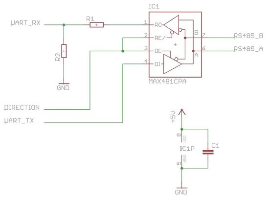
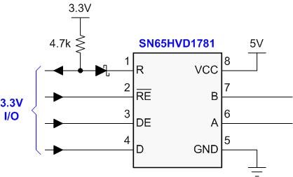
I have to interface the UART(RS232) interface operating at 3.3V logic levels (from processor) to RS485 transceiver(SN65HVD1781) operating at 5.0V connected to TTL level interface.  For the mentioned purpose can I use a level converter(suggest part number) or directly I can connect RS232 signal RS485 transceiver. 

Thanks and regards

-Anand

  • Anand,

    RS232 and RS485 differ in electrical specifications and their signals cannot be connected directly.

    From your description, i understand that you have a microcontroller operating on 3.3V and a RS485 transceiver operating at 5V.

    If you see parameters VIH, VIL, VOH, VOL in the datasheet, it can be seen that  the UART Transmit can safely be connected to the D input of the SN65HVD1781, while a potential divider will be required between the R output and the UART Receive input.

    The RE\ and DE pins can be connected together and controlled by a single port pin.

    Hope this helps..

    Regards,

    JayantD

  • Anand,

    can you give me a part number of the UART, some 3V devices have 5V tolerant inputs. If not you might need a voltage-divider or a current-limiting resistor (the latter one is the cheap not-so-clean solution but works).

    UART outputs have nothing to do with RS-232 levels. They are logic levels interfacing into the logic side of either RS232 transceiver, RS-485 transceivers, CAN transceivers, etc. The transceiver then do the conversion to the standard specific signal-voltage levels.

    Regards, Thomas 

  • Hi

    Thanks Thomas and Jayant for your quick replies.

    My UART output is from form i.MX287 processor from Freescale. Using a voltage divider is nice idea but it will continuously consume steady current. Again I think, bidirectional logic conversion will be required at Tx 3.3V to 5V and at Rx 5V to 3.3V. I am attaching a word file for more clear reference.

    6215.New Word 2007 Document.docx 

    Thanks and regards

    -Anand

  • The voltage divider will draw current only when RO is logic high.

    Hope this helps..

    JayantD

  • Anand,

    Firstly, thank you for selecting the SN65HVD1781 over the MAX481.

    Secondly, you don't have to waste power with a resistive voltage divider. You are correct in that a current only flows when R = High. But that is exactly the point. It is common to indicate a bus-idle state through logic High. In this case you would have current flowing while your data link is idle, which doesn't seem right.

    A simple solution is to convert the push-pull receiver output into an open-drain type output using a small-signal schottky diode. Then connect a 4.7k pull-up resistor between the receive data line and the 3.3V UART supply. Now current only flows (c.a. 600uA) when R = LOW.


    Good luck and let me know how it goes.

    Kind regards, Thomas

    ( Apps.Mgr. , Industrial Interfaces, TI)

  • Hi!!!

    Thanks Thomas and Jayant for your suggestions.

    Best Regards

    -Anand

  • Hello Thomas,

    Thanks for the circuit idea.

    I have a query.. will the switching time of the schottky diode affect the max baud rate offered by the part ? Can you suggest suitable schottky diodes ?

    Regards,

    JayantD

  • Hi!!!!

    After analysing the circuit, what I find is my processor will get a logic high when logic is actually low at receiver and vice-a-versa in when logic is high. But, I agree with Jayant question "will the switching time of the schottky diode affect the max baud rate offered by the part". And yes please do suggest some suitable schottky diodes.

    Thanks and regards

    -Anand

  • 1) Use BAS40SL (typ Cd=5pF)

    2) Yes diode capacitance will affect your baud rate. calculate your times-constant via RxC, and because you only draw current during LOW you can make R small if you need high data rates. You only need 1 TC to drop 70% from High to low which in this case is ~ 24ns.  90% of RS485 applications is below 1Mbps. How fast is yours? 10Mbps? then drop the rsistor to 1k or 0.47k.

    3) Analysis:

    When R=LOW it forward biases the diode and current flows from 3.3V thgough the diode and the lower transistor of the push-pull output stage towards ground.

    When R = High, the diode is reversed biased and does not conduct. Vcc potential is now on your data line.

    Aloha,

    Thomas

  • Hi Thomas!!!!!!!!!!

    Thanks for the more clear explaination and your support.

    Thanks and BR,

    -Anand 

  • Thomas,

    Thanks for the support.

    Regards,

    JayantD

  • Hi Guys, (Anand & JD)

    I can you an even better performaning Diode resistor pair in form of a 10k resistor and a BAT54 (low-cost) schottky.

    The timing (including minor overshoots) looked nioce even at 10 Mbps.

    One heck of a schottky is the BAS60 (for decades) but it comes in a Glass Mini-MELF package and hence, if you don't have the tools, will role off your board.

    Cheers, Thomas