TCAN2451-Q1: SPI Communication

Part Number: TCAN2451-Q1
Other Parts Discussed in Thread: SYSCONFIG,

Tool/software:

Hi,

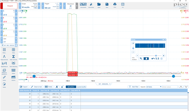
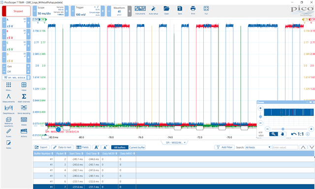
   I working on TCAN2451-Q1 SBC Chip, just configured the SPI lines in sysconfig , with active low chip select  and the bitrate configured is 500kHZ. My first target is to read the Device id register and also to read SPI Config register from SBC chip. While i am reading from the Chip, the simple code is attached here

GPIO_writePin(SPI_CS_GPIO_PIN, 0);

DEVICE_DELAY_US(500);

data_address = ((0x04 << 1) | 0x00);
SPI_writeDataNonBlocking(SPID_BASE, data_address);

DEVICE_DELAY_US(500);

GPIO_writePin(SPI_CS_GPIO_PIN, 1);

while(SPI_isBusy(SPID_BASE));


Sbc_out = SPI_readDataNonBlocking(SPID_BASE);

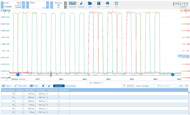
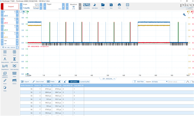
I am getting the Sbc_out value as 0x6043, and even if i read the register for SPI_Config which is 0x09, i am getting the same output value.

Can you please suggest if any init sequence for initially to be followed and read the SBC SPI lines.

Please note that from hardware side VCC1 and VCC2 is ON

  • Hi Naveen,

    There is no special sequence to start writing SPI commands - you just need to be in at least standby mode - which if VCC1 and VCC2 are on and are stable you are in standby mode (if you have just powered on device - VCC1/VCC2 will also be on in Normal mode - but the IC needs to go through standby mode before a SPI command forces device into normal mode)

    Do you have the SW pin pulled high externally while running this test?

    Could you potentially capture a scope shot of the SPI bus - I am interested in all 4 of the signals. I just want to make sure nothing looks strange electrically or time wise. 

    If you could also check by reading the following addresses and seeing what data you get back:

    Addresses to read: 51h, 52h, 53h, 54h, 55h, 5Ah, 5Ch 

    These are the interrupt registers and I just want to check if you are getting valid information or what interrupts are being flagged - that can help me understand the device a little bit more or at least allude to a different problem (i.e. if an interrupt triggered could not have been actually triggered it will help me determine if there could be something wrong with the IC itself)

    Please report back to me with the requested information - or whatever you are able to get for me and we will take it from there to try to pin down a solution to this issue for you. 

    Best,

    Parker Dodson

  • Hi Parker,

            Can u clarify , how to check the SBC in Normal Power mode , as per the datasheet Register 0xC should give the SBC whether it is in Normal mode or standby mode.

    Do you have the SW pin pulled high externally while running this test?

               SW Pin is Pulled high in hardware.

    If you could also check by reading the following addresses and seeing what data you get back:

    Addresses to read: 51h, 52h, 53h, 54h, 55h, 5Ah, 5Ch 

    Green is Clock, Red - SDI , Yellow - SDO, Blue - CS

    ...

                          In the above screenshot , in between blue line is the CS Pin made high and low. After that i tried to send the consecutive commands of 

    register read like 0x04, 0x51 , 0x52, 0x53, 0x54, 0x55 , between the each of these register read i given delay of 500US which is mentioned code 

    /**************DeviceID Read**********************/

    GPIO_writePin(SPI_CS_GPIO_PIN, 0);

    DEVICE_DELAY_US(500);

    data_address = ((0x04 << 1) | 0x00);
    SPI_writeDataNonBlocking(SPID_BASE, data_address);

    DEVICE_DELAY_US(500);

    GPIO_writePin(SPI_CS_GPIO_PIN, 1);

    while(SPI_isBusy(SPID_BASE));


    Sbc_out = SPI_readDataNonBlocking(SPID_BASE);

    /**************InterruptRegister Read(0x51)*************/

    GPIO_writePin(SPI_CS_GPIO_PIN, 0);

    DEVICE_DELAY_US(500);

    data_address = ((0x51 << 1) | 0x00);
    SPI_writeDataNonBlocking(SPID_BASE, data_address);

    DEVICE_DELAY_US(500);

    GPIO_writePin(SPI_CS_GPIO_PIN, 1);

    while(SPI_isBusy(SPID_BASE));


    Sbc_out = SPI_readDataNonBlocking(SPID_BASE);

    /***********InterruptRegister Read(0x52)*********/

    GPIO_writePin(SPI_CS_GPIO_PIN, 0);

    DEVICE_DELAY_US(500);

    data_address = ((0x52 << 1) | 0x00);
    SPI_writeDataNonBlocking(SPID_BASE, data_address);

    DEVICE_DELAY_US(500);

    GPIO_writePin(SPI_CS_GPIO_PIN, 1);

    while(SPI_isBusy(SPID_BASE));


    Sbc_out = SPI_readDataNonBlocking(SPID_BASE);

    and so on for upto 0x55 register read.

    For Read of Device ID , we got output in Sbc_out 0x1D18

    Read of Int_Reg(0x51)Read, we got output of 0x4D77

    Read of Int_Reg(0x52)Read, we got output of 0x2AEF

    Read of Int_Red(0x53)Read, we got output of 0xCA35

    So like these with respect to register read we didn't got the specific output of register, we got some random value of response.

    Can u please explain why this is happening.

    After this observation we tried to replace with another IC also, it was giving the same response.

    Please kindly help me for the further step of process

    Green is Clock, Red - SDI , Yellow - SDO, Blue - CS

  • One Screenshot got missed , i am attaching here 

    Green is Clock, Red - SDI , Yellow - SDO, Blue - CS

  • Hi Naveen,

    To check if SBC is in normal mode you just read the SBC mode config at address Ch . If bits 3-2 are set to 0b10 then the device is in normal mode. Standby mode would read 0b01. 

    That being said - did both devices that you tested send back an odd number for byte 2 on a read from 53h? 

    I am asking because you are getting a CRC_EEPROM error - which would explain why the data you are getting is junk because the interrupt outputs do not make any sense with what you are getting.  

    Also - are you attempting any custom EEPROM programming on the device or have you at all? I don't believe you have - but I just want to verify.  

    Could you also attach a picture of both units you tested - I want to be able to trace the part marking back to see what information about the parts you have I can find. 

    Best,

    Parker Dodson

  • Hi Parker,

    So whatever we have tested with above previously, we pulled up all these lines by pullup resistor of 100k ohm and then after by 62kohm. So whether external pull up's are required for all the SPI lines. 

    These pullup resistors we initially did, because the chip was going over to Low power mode every time while we do debugging, so that's why we pulled up all lines with the resistor. Then after chip didn't went to low power mode.

    After yesterday data collection logs for you, then we tried to check the voltage for SPI lines, it's somehow got shorted SPI lines when we probed those test points. Sorry for the inconvenience caused.

    So from this morning we are doing some analysis with another fresh board.

    So while we checked the other board without pull up resistors, clock, SDI and SDO cannot able to get proper signal. So whether external pull up resistor actually required.

    In new board Clock is pulled up with 100k resistor

    While we are sending data, SDI lines (red) cannot able to see properly in data communication, i am attaching one of sample of SDI data miss.

    Blue - CS, Red - SDI, Green - Clock, Yellow - SDO

    Sometimes Clocks are missing, even though we have externally pulled with 100k

    In one of the case of read request of interrupt register (0x55), i can see the SDI line with below attached one

    By this, if i collect and send my observation of data whatever u requested it will be completely improper. So can you try to recheck once the schematic design and post your observation, whether any pull up resistor required for these lines or not.

    I am attaching the support forum ticket which has been done review by you.

    TCAN-2451_SBC_Schematic

    After your review of Schematic, we have updated the same, for your reference attaching the updated schematic

    Kindly review and post your observation

  • Hi Naveen,

    I have to check a few things with my internal team - I will have more information for you tomorrow. 

    I appreciate your patience here. 

    Best,

    Parker Dodson

  • Hi Naveen,

    I sincerely apologize for the delay here - I was unexpectedly out of office yesterday as to why there has been a bit longer than anticipated delay. 

    You don't need pull-ups on the SPI lines. You may need a pull-up on the nCS pin if the controllers nCS pin is open drain/open collector - but the SBC does not require you to add pull ups on the SPI lines.

    It is recommended to have a pull-up to VCC1 on SW pin during initial debug to prevent device from restarting due to missed watchdog triggers - after watchdog triggers have been implemented this pull-up isn't needed anymore. 

    The SCLK, SDI signals are coming from whatever controller/tool you are using - if they are missing clock signals or are not sending proper SDI signal configuration that is not the SBC that is causing issues. I can't debug the SPI tool/controller you are using - but the SPI signals are invalid so I can't debug the issues until you are able to generate correct SCLK and SDI pulses consistently as I am not able to help you debug the SPI issues. 

    From what you have shared of schematic it was reviewed correctly - but anything that you do not show I never reviewed so I cannot be sure it is correct. 

    For now I am closing this thread because the issue is most likely due to bad SPI signals that are not originating from the SBC - if you fix your SPI input signals into the SBC and they are consistent and you are still seeing issues you can re-open the thread at that time - but at this point if the SPI signals sent to SBC are not correct the problem needs to be fixed there before we can attribute any of these issues to the SBC or how it is being used. 

    Best,

    Parker Dodson

  • Thank you parker for the reply, as we will again see what can be possible method can be tried from our end. If the issue persists we will report back to TI Support team of India.

  • If the SPI signals from the controller look okay and you are still having SPI issues please come back here and we can take a look - but it is impossible to determine if the SBC is the source of the issue - it still could be having issues but other devices upstream are too at this time. 

    Please come back if you have any more questions on the SBC specifically. 

    Best,

    Parker Dodson

  • Hi Parker,

        I was on leave last week, we will check once with SPI Signals and get back to you.

  • Hi Naveen,

    Alright -no issue. 

    Best,

    Parker Dodson