This thread has been locked.

If you have a related question, please click the "Ask a related question" button in the top right corner. The newly created question will be automatically linked to this question.

PCF8574: PCF8574 and npn transistor

Part Number: PCF8574


Hello, i have a custom pcb with an arrange as follows

image.png

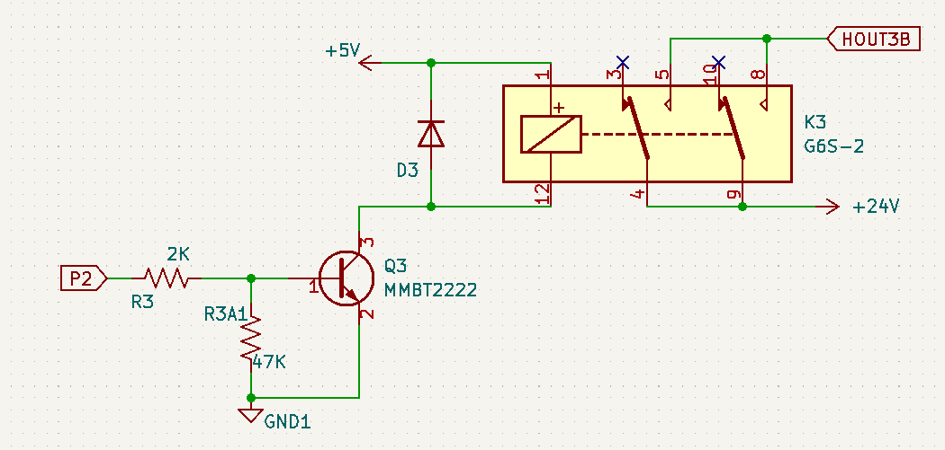
p2 is a PCF8574 pin.

when put in HIGH a voltage about 0,75V is read betwen R3 left side and GND. Not enough to activate MMBT2222.

can be this fixed removing R3A1?

any advice will be apreciated.

Br

Juan


  • Hello, I confirm that MMBT2222 is driving fine the relay K3.

    Voltage at P2 still being 0,75V when HIGH.

    Is this a safe situation for long time?

    Should be better to remove R3A1?

    Br

    Juan

  • Hi Juan,

    We are still looking into this and will provide a response soon.

    Regards,

    Jack

  • Hi Juan,

    PCF8574 has a weak pull-up FET. Its IOH is between 30 uA and 310 uA. 

    The resistive divider circuit looks to source 5 V / (47000 + 2000) = ~102 uA. 

    This might be the reason why when you decide to drive HIGH you only read a voltage of 0.75V. Consider using an I/O expander with stronger PU drivers such as the TCAL6416PWR. Its IOH can drive several mA. 

    Regards,

    Tyler

  • Hello Tyler, thanks

    I removed the 47Kohm resistor, the relay now it's switching very well (before there was a strange noise).

    Voltage remains at 0,75/0,8V.

    Is this reliable for long term operation?

    Regards

    Juan

  • Hi Juan,

    What is the part number for your transistor? 

    What is the base-to-emitter voltage? 

    Regards,

    Tyler

  • Hello, transistor is JCST MMBT2222A 1P.

    with pcf8574 pin HIGH 0,6v between base and emitter

    5v relay coil requires 28mA

    Br

    Juan

  • coil resistance is 178ohm (not sure if it's a relevant info for you)

  • Hi Juan,

    So from my understanding of the datasheet, the range of base-to-emitter saturation voltages can be 1.2 V to 2 V max. 

    The output high voltage of PCF8574 may just barely be reaching the acceptable range of VBE with its output high voltage. 

    Removing the 47k to GND would eliminate that excess current leakage path. You might also try reducing the 2k gate resistor to something less, 500 ohms, to see if this improves the VOH at the gate.

    Regards,

    Tyler

  • Hello, relays are switching fine even with a voltage about 0,7 at npn transistor base.

    I tried changing 2k resistor by 500ohm resistor, no change.

    Something wired is as soon as 3v3 is applied at pcf8574 vdd output 1 is high until I put in LOW by software.

    Is this reasonable?

  • forgot, R80 was removed because of flash interference with esp32 gpio12. Interrupt pin is not required as not reads are not required, just write HIGH or LOW. Can be this a problem? gpio12-int connection could be complete removed

  • Hi Juan,

    Something wired is as soon as 3v3 is applied at pcf8574 vdd output 1 is high until I put in LOW by software.

    This seems reasonable.

    The device should power on with the GPIO's as inputs. In order to setup the IO as an input, you write to the device all 0xFF. This is the default state on power up, so as soon as 3V3 is applied output 1 is high until you drive LOW through the I2C write. 

    forgot, R80 was removed because of flash interference with esp32 gpio12. Interrupt pin is not required as not reads are not required, just write HIGH or LOW. Can be this a problem? gpio12-int connection could be complete removed

    /INT can be left floating as this is an open-drain output.

    P2 should not be left floating if used as an input. 

    Regards,

    Tyler

  • Hello Tyler, thanks for feedback. Just to be sure:

    I use P0/1/2/3/4/5 as outputs, P6/7 are not used, interrupt either.

    During power up only P1 is high until is put LOW by software. If and actuator is controlled by this pin this will be out of control a few seconds.

    Is this expected behavior just for P1 and not the rest of the outputs?

    How to avoid this?

    Br

    Juan 

  • I will respond soon.

  • Hi Juan,

    During power up only P1 is high until is put LOW by software. If and actuator is controlled by this pin this will be out of control a few seconds.

    The PCF8574 device powers on with a weak PU source to VCC. It is about 100 uA of current strength. This would be equivalent to 10's of kohm of PU strength. Each IO powers up this way. 

    This 100 uA current source can be overcome by sinking current externally from a device. This is how the IO is driven LOW by some device elsewhere in the system. 

    I would say this is expected behavior is you can determine ~ how much current is being sunk on each pin externally. If you need a stronger pull-high to VCC, consider adding external pull-up resistance to keep the IO at a stronger logic high state. 

    Regards,

    Tyler