This thread has been locked.

If you have a related question, please click the "Ask a related question" button in the top right corner. The newly created question will be automatically linked to this question.

CSD87502Q2: CSD87502Q2: CAN terminal control using GPIO control

Part Number: CSD87502Q2
Other Parts Discussed in Thread: TIDA-01238

Hello,
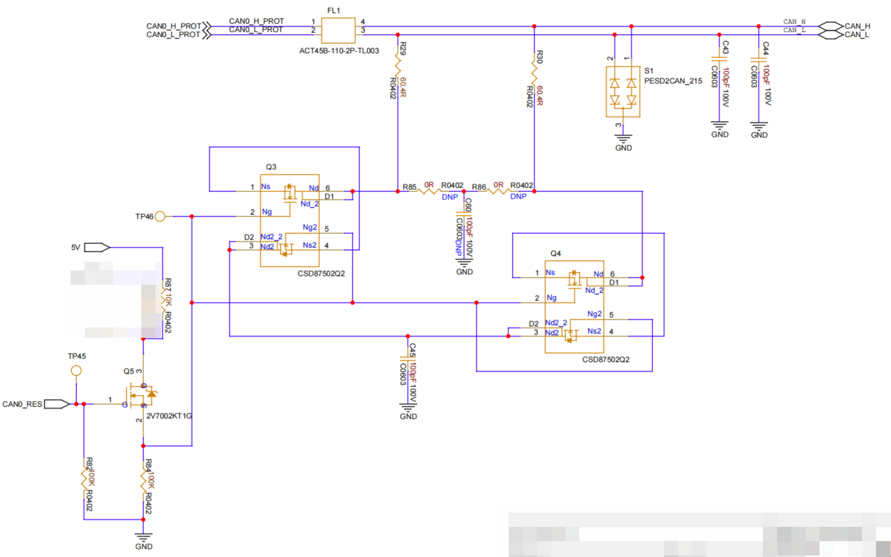
       We are using your company's CSD87502Q2 device as a CAN terminal control switch. The gate drive voltage is 5V, and we have measured that the MOSFET is conducting. However, why is the terminal resistor not measured as being connected? 
DESIGN.png
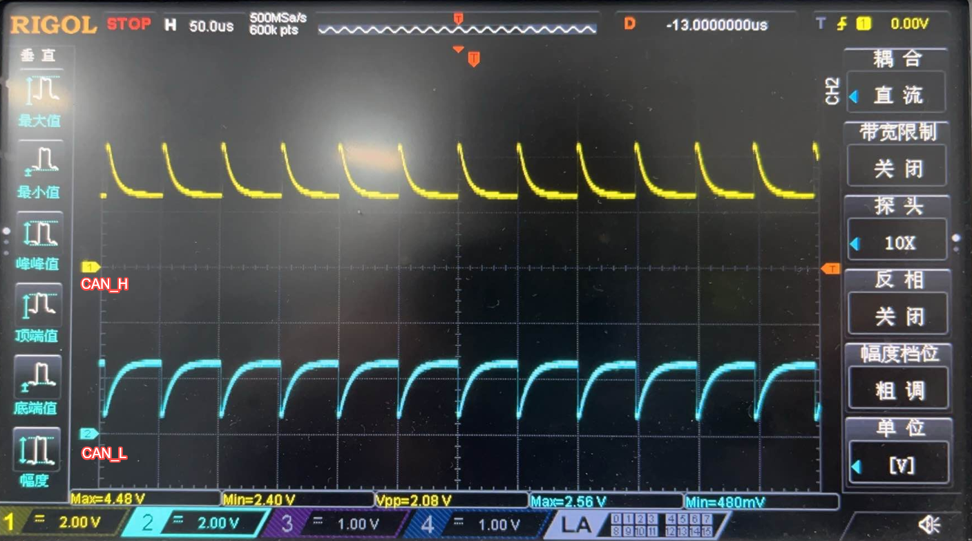
Test the CAN_H and CAN_L signal waveforms after the MOSFET is turned onTEST.png
 
  • Hello Emma,

    Thanks for your interest in TI FETs. I am not familiar with this type of application. From the schematic, I can see that all of the gates are tied together and are driven off of the source of Q5. When Q5 is on Vgate = 5V x (R84/(R84+R87)) = 5V x (100k/(10k+100k)) = 4.55V. I also see that the sources of Q3 are tied together and the sources of Q4 are tied together. However, the source terminals of Q3 and Q4 are floating and not referenced to GND or another voltage. What is VGS? Can you provide VGS waveforms? In order to turn on the FET, VGS ≥ 3.8V, the lowest value where Rds(on) is specified in the datasheet. What are the expected waveforms at CAN_L and CAN_H? Are they supposed to be square waves? I look forward to your response.

    Best Regards,

    John Wallace

    TI FET Applications

  • HI: The gate-source voltage VGS meets the requirement of ≥3.8V. The expected waveforms at CAN_L and CAN_H should be square waves after the terminal resistor is connected. However, the current measurement results show that when measuring Q3 and Q4 individually, both MOSFETs can be turned on, but the voltages measured at CAN_L and CAN_H still present the waveforms as if no terminal resistor is connected. Please help confirm the specific reasons. Thank you for your support.

  • HI  John Wallace:

           Our design has referenced your company's same MOS switch circuit, but the test waveforms on our side are different from those of your company. Could you please help consult and confirm this?

    tiducf3.pdf

  • Hi Emma,

    Thanks again for your interest in TI FETs. I was not involved in the TIDA-01238 reference design. I am going to reassign this thread to the interface applications team to ask them to review your schematic and questions. I will continue to monitor this thread and respond as needed.

    Thanks,

    John

  • Hi Emma,

    Measuring 4.5 V gate vs GND may not be sufficient enough. I.e., if the FET's source node is floating at some intermediate CAN voltage, the actual VGS may be too small to turn ON. Hence, it appears to conduct when measured in isolation / separated but not when connected / measured with CAN. I suspect this is due to the CAN nodes where CAN common mode voltage typically resides around 1/2 VCC or 2.5 V recessive.

    • Confirm V_GATE driving Q3 and Q4
    • Confirm V_SOURCE connecting CANH or CANL.
    • Confirm VGS = V_GATE - V_SOURCE as the expectation is to be ≥ the data sheet's spec of 4.5 V or at least 3.8 V for example, to ensure the FET is fully ON.
    • May also measure the voltage across the termination resistor.

    You would likely notice the gate goes to 4.5 V but the source near 1/2 VCC, implying VGS near 2 V as the most likely root cause and would recommend changing the gate drive to produce VGS in the expected range by removing / changing the divider network so the get sees the full 5 V and also ensuring source is low enough to produce the required VGS. May also consider a FET with a lower Rdson at lower VGS spec, if not feasible.

    • Also ensure R85/86 are populated to double confirm the drain / source are connected to the termination.
    • May also double confirm there are no body diode orientation issues. See if current flows as expected when a small current is applied from CANH to CANL through a safe resistor while gate is driven I.e., if the body diode blocks it, thanks.

    Best Regards,

    Michael.