LSF0108: Logic forum

Part Number: LSF0108
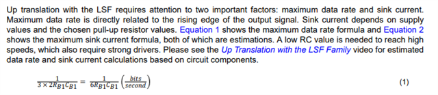

Hi all,

In our customer's 3.3 V to 1.8 V conversion line, overshoot that did not occur in the prototype occurred in the second prototype.The left is the signal waveform with no problem, and the right is the waveform with overshoot.
The phenomenon follows LSF0108. Also, there is a difference in marking between these devices.


1) What is the difference between them?
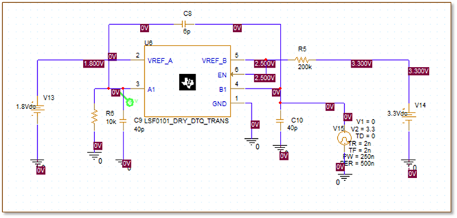
2) Please tell me the specific cause and countermeasures.We, the distributor, conducted a simulation and found that there is a difference due to capacity. For this phenomenon, the peak voltage is lowered by placing a series resistor, but the constant cannot be determined.
3) Is this understanding correct? Is the countermeasure for this problem to place a series resistor as a way to suppress the rise time? If so, what is the constant of the resistor?
4) Please let me know if there is another countermeasure.


Best Regards,

Ryusuke

  • Hi Ryusuke-san,

    1. There isn't any differences between them other then the assembly lot from these two units. 

    2. Can we confirm the test setup was the exact same with similar probes used and board/ soldering conditions? 

    3. Yes, dampening resistors can be placed at the outputs of the device to decrease slew rate and reduce overshoots observed. The value is different per every setup, however it is suggested to start at stronger value (i.e 20ohms) and increase ohmage until overshoot % is acceptable per application requirement. 

    Regards,

    Jack

  • Hi Jack,

    Thank you for your reply.


    Overshoot cannot be improved unless the rise time is set to 200 ns during simulation.
    To obtain the transition time of 200 ns, I think it is determined by the time constant of series resistance and Ci.
    Therefore, if Ci inside the IC is not specified, the constant of series resistance cannot be determined.

    1) Please tell me how to determine the constant of series resistance.

    2) Ci is stated as 40 pF in the data sheet. Please tell me how much variation there is and its σΣ value.

    3) What is the relationship between Cin and Con? The data sheet describes Ci and Cio (On) as follows.

    Isn't it wrong that the value of Cio (On) is lower than Ci (EN)?

    Please tell me the correct value.

    When determining the series resistance constant, I think it would be confusing if the value of Ci is wrong.

    Thank you and best regards,

    Ryusuke

  • Hi Ryusuke-san,

    The output transition rate is dependent on the RC time constant formed by the external pullups and capacitive load associated with the output. This formula provide in the datasheet can be used as a reference to estimate what is the max achievable data rate given these external conditions: 

    The Cio parameter you have pointed out is providing the detail of the capacitance of the switch itself. Cload (output capacitance) would play a much bigger role here in the output transition rate. 

    Regards,

    Jack

  • Hi Jack,

    This incident was confirmed only in the down conversion line from 3.3 V to 1.8 V.

    What is expressed as overshoot is the waveform appearing at the rising edge.

    I understood that it is important to check the output capacitance Cloud during down conversion, and Cio is a value to be ignored for Cloud.

    Specifically, how many Ω of series resistor is required for how many F of Cloud?

    It is necessary to completely suppress overshoot for the input terminal capacitance.

    I send the simulation result with Ci=40 pF referring to the data sheet.

    When the rise time of the input waveform was changed from 2 ns→100 ns→200 ns, we thought that overshoot could be avoided at 200 ns.

    In order to make the rise time more than 200 ns by using a series resistor, we confirmed that about 1 kΩ is necessary from the relationship between the resistance value and the rise time.
    This is on the assumption that Ci=40 pF (typ). Therefore, we think that overshoot may occur when Ci is small.
    Do you have any information about the variation of Ci?

    I am sorry, but I am in a hurry to answer. I would appreciate it if you could answer tomorrow.

    Best Regards,

    Ryusuke

  • Hi Ryusuke-san,

    We are still looking into this and will provide a response soon.

    Regards,

    Jack

  • Hi Jack,

    Thank you for your prompt response and reply.

    I look forward to your reply.

    Best Regards,

  • Hi Ryusuke-san,

    Unfortunately the variation for the CIO parameter is only what has been detailed in the datasheet. The series resistor value implementation would require the evaluation of different values as there is not a standard procedure to finding this value per your setup. The use of pullups on the output (1V8 side) would also help to maintain logic high state of 1V8 and reduce the overshoot. (Please note pulldowns are not recommended to be used with this device).

    Additionally, I would suggest evaluating the device with the EVM: www.ti.com/.../slvub53.pdf

    Regards,

    Jack

  • Hi Jack,

    We have confirmed that the overshoot decreases as the series resistance value approaches 1k. Since this is a confirmation result of an actual machine, if we

    do not know the min of the input capacitance due to IC variation, we cannot know the allowable resistance value min.

    Also, if we do not know the max of the input capacitance, we cannot know the allowable resistance value max.

    1) I would like to clarify whether the input capacitance changed due to the difference in lots.

    Through simulation, we understood the possibility that the waveform of the event could be reproduced due to the difference in input capacitance, but it is not

    clear whether this is the cause of this incident. I would like to know the cause.

    2) I would like to know the variation in the terminal input capacitance of LSF0108, especially the smallest value. This is because it is necessary to limit the rise

    of the 3.3 V driver in order to improve the overshoot of the 1.8 V output terminal, and we are considering a design to provide a series resistor for this purpose.

    The value of the series resistor is determined by the input terminal capacitance of the IC.

    If the input capacitance is small, the rise time becomes short, and overshoot is likely to occur.

    If the input capacitance is large, the rise time becomes long, and timing requirements may not be satisfied.

    Therefore, it is necessary to understand the variation (median and standard deviation) of the terminal capacitance in order to design all products to operate stably.

    Best Regards,

    Ryusuke

  • Hi Ryusuke-san,

    The information you are looking for (variation on the Cio values) is not production tested, and only provided as- per in datasheet to aid system designers therefore we do not have data you are looking for. If you believe that the units have been damaged/ quality issue concerned related, then it is suggested to create return case with your local TI- representative for further analysis. 

    Customer may also refer to the Logic Minute video series that provides a deeper look into the LSF family and how these devices operate, as well as the critiera of concern for transition rates: https://www.ti.com/video/series/understanding-the-lsf-family-of-bidirectional--multi-voltage-lev.html

    Regards,

    Jack

  • Hi Jack,

    Thank you for various answers.
    I understand that there is no data about CIO variation.
    Please tell me the definition of the parameters described in the data sheet.

    CIN : Input capacity of EN terminal

    CIO(off) : "Input terminal capacity when off" or "Terminal capacity between input and output"

    CIO(on) : Input terminal capacity when on

    Which is the definition of CIO (off)?
    If it is the input terminal capacity when off, I think I can get the answer because MAX is shown.

    CIO(on) means that the terminal capacity is connected in parallel and the capacity existing in the IC internal path is added.
    I understand that CIO (off) cannot be greater than CIO(on).

    Therefore, I pointed out at the beginning that the values of CIO (off) and CIO(on) are interchanged by the typo.
    If these parameters are interchanged, I think it is easy to understand that it is 10 pF Max.

    Best Regards,

    Ryusuke

  • Hi Ryusuke-san,

    CIO on/off refers to the capacitance at the I/O terminal of the device with the input condition that establishes the high-Z state at the output. In other words, this parameter is the internal capacitance encountered at an input/output (I/O) of the device. 

    The spec you referred to at Ci (EN) is higher then CIO because this is the capacitance at the gate of the internal FET of the device. IT should not be factored in your calculations as it is not the capacitance associated to the I/O port. 

    Regards,

    Jack