TCAN4551-Q1: SPI speed

Part Number: TCAN4551-Q1
Other Parts Discussed in Thread: TCAN4550,

Hi experts,

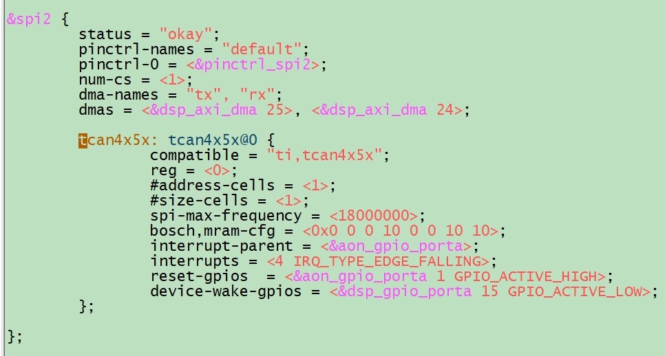
customer will meet the write: No buffer space available error when linux and PC exchange message every 100ms through TCAN4551. Below is customer X5M Linux platform dts configuration. the SPI speed is 18MHz. Is there any problem?

11.jpg

  • Hello Kevin,

    The maximum supported SPI frequency is 18MHz.  The OSC crystal/clock frequency should be at least 2MHz faster than the SPI clock frequency so the OSC crystal/clock frequency would need to be 20MHz or greater.

    As long as the OSC clock is at least 20MHz and the processor can maintain good signal integrity with 18MHz, then there should not be a problem.

    Regards,

    Jonathan

  • Hi Nerger,

    customer use the X5M platform and the Linux kernel version is 6.1.83. Does our TCAN4X5X driver need update? customer current OSC is 40MHz, SPI is 16.6MHz. They need at least 1Mbps data rate. Is any other reason to result this issue? Thanks.

    frequency

    schematic

    error

  • Hi Kevin,

    As explained in the Software Optimization Tips (section 5) of the TCAN45xx Software User's Guide (Link), the most common issue that hurts CAN throughput is the SPI throughput.  There is a lot of data that needs to be transferred through the SPI bus and therefore the overall time needed to transfer all of data through SPI becomes the determining factor for how fast CAN messages can be received without running out of buffer space and loosing a message.

    Reducing the idle time between SPI reads, having an efficient SPI driver that doesn't contain a lot of idle time within a transaction such as the delay between chip select transitions and the beginning and end of the data transfer, or using multi-word data writes and reads when possible instead of multiple single-word writes and reads, etc. will help optimize the overall message throughput.

    I would recommend connecting a logic analyzer to the SPI lines and capture the SPI traffic to determine the overall time your processor needs to fully process and acknowledge a received CAN message.

    The SPI interface is both a benefit and drawback of the TCAN4550.  The benefit of it is that it can be used to add a CAN FD interface to any processor that has a SPI peripheral but not a CAN FD peripheral.  The drawback is that the SPI interface is a slower interface to the processor and not as efficient as using a CAN FD controller peripheral that is internal to the processor itself.

    Regards,

    Jonathan

  • Hi Jonathan,

    The above issue has been solved. Thanks for your support. But there is another issue below:

    Approximately 1300 classic frames with 29 bit identifier per second (17% bus load).

    The problem occurs a few times / second, example:
    [  898.598808] tcan4x5x spi2.0 can0: msg lost in rxf0

    [  899.288902] tcan4x5x spi2.0 can0: msg lost in rxf0

    [  899.600075] tcan4x5x spi2.0 can0: msg lost in rxf0

    [  899.610051] tcan4x5x spi2.0 can0: msg lost in rxf0

    [  899.620749] tcan4x5x spi2.0 can0: msg lost in rxf0

    [  899.792517] tcan4x5x spi2.0 can0: msg lost in rxf0

    [  901.794157] tcan4x5x spi2.0 can0: msg lost in rxf0

    [  901.993276] tcan4x5x spi2.0 can0: msg lost in rxf0

    [  903.192733] tcan4x5x spi2.0 can0: msg lost in rxf0

    [  904.294165] tcan4x5x spi2.0 can0: msg lost in rxf0

    [  904.797175] tcan4x5x spi2.0 can0: msg lost in rxf0

    [  907.747316] tcan4x5x spi2.0 can0: msg lost in rxf0

    [  907.802550] tcan4x5x spi2.0 can0: msg lost in rxf0

    [  908.298828] tcan4x5x spi2.0 can0: msg lost in rxf0

    [  908.802312] tcan4x5x spi2.0 can0: msg lost in rxf0

    [  909.749122] tcan4x5x spi2.0 can0: msg lost in rxf0

    [  909.803416] tcan4x5x spi2.0 can0: msg lost in rxf0

    Is there any reason? Thanks.

  • Hi Kevin,

    I believe this is the same issue.  The processor has allocated a particular number of RX Buffer Elements for use in the RX FIFO 0.  As CAN messages are received, they are stored into the RX FIFO starting with the first element, then the second and so forth until the last element has been used.  This is indicated by the Put Index in the RX FIFO 0 Status Register.

    Meanwhile the processor should be reading the the RX Buffer Elements starting with the lowest number element first which is indicated by the Get Index in the RX FIFO 0 Status Register.  Messages should always be read in the order they are received. After a message, or messages, have been read, the processor must write the Buffer Index number  of the last buffer element that was read to the RX FIFO 0 Acknowledge Register to indicate which buffer elements in the RX FIFO 0  are available for new messages.

    RX Messages can be read and acknowledged one at a time, or multiple messages can be read and then acknowledged, or cleared together.  Just understand that the message buffer will remain occupied until it has been Acknowledged by a write to the RX FIFO 0 Acknowledge register.

    So when the device receives a new message after it has filled the last RX buffer element in the FIFO, it will cycle back around to the first message buffer element.  If this element has been acknowledged or cleared, then it will store the new message into the element and the cycle repeats. 

    However, if a new message is received and all RX FIFO elements are still occupied, then a message will be lost.  There are two operation modes to chose from in the RX FIFO 0 Configuration Register which are either Blocking Mode or Overwrite Mode. 

    If Blocking mode has been configured, the new RX message is blocked from being stored in the FIFO and it will be lost.  The oldest message is retained.

    If Overwrite mode has been configured, the RX buffer element is overwritten with the new message and the oldest unread message will be lost.  By default blocking mode is configured.

    So again the key point in our conversation is that the processor needs to be able to read and acknowledge the RX messages through the SPI interface faster than the CAN messages are being received in order to avoid the RX FIFO becoming full resulting in a lost message.

    Regards,

    Jonathan

  • Hi, Jonathan

    Please let us know the mram configuration for the fastest communication.

    Also please let us know how to enable the burst mode/ bulk read.

    Regards,

    Roy

  • Hi Roy,

    The TCAN45xx Software User's Guide (Link) provides examples of how to configure the MRAM and to optimize the SPI communication.

    The burst mode/ bulk read at the SPI driver level is changing the Length field of the SPI message header to indicate how many words of data will be transferred before the chip select signal is pulled high.  

    The datasheet SPI Write and Read diagrams already show a 2-word write with the Length field set to 2.  If you notice there is a total of 8 data bytes transferred which is equivalent to 2 words of data. Each word is equal to 4 bytes or 32-bits.

    The Address field is then the "Starting Address" of the first word of data to be transferred.  One example of this in use is to read the entire contents of a Received CAN message from the MRAM buffer element.  You would simply provide the starting address of the RX buffer element and how many total words of data the buffer holds.  As long as the MCU provides the correct number of SPI clock cycles and holds the chip select line low for the entire transaction, there is no need to perform multiple SPI reads to receive that message.

    Likewise you could write the entire contents of a CAN message to a TX buffer element in a single SPI Write transaction.  

    Regards,

    Jonathan

  • We are using the m_can and tcan4x5x drivers included with the Linux kernel 6.1.83, which already use burst mode by default. What else can we do? Could you provide us with a ready-to-use kernel driver patch directly?

  • Hello Roy,

    The TCAN4550 is supported at the device level in this forum and I can't provide any Linux updates or patches.  The driver has been updated and optimized to the extent possible by Software developers with Linux expertise.  

    There are no additional enhancements specific to the TCAN4550 beyond those already included in the current driver.  I would suggest looking for improvements to the SPI driver and any delays or inefficiencies in the run time execution of the processor. 

    - Use the fastest SPI bit rate that can be supported by the processor and TCAN4550, (18MHz is the max guaranteed bit rate for the TCAN4550)

    - Reduce any idle times within the SPI message frame that could be adjusted in the processor's SPI driver.

    - Optimize the run time execution and the time needed between detecting a CAN message has been received and responding to it.  

    Regards,

    Jonathan

  • Hi Jonathan,

    The following are the issues encountered by our customer:

    "------------------------------------------------------------------------------------------------------------"
    I have a PC running linux with a Kvaser CAN-dongle connected to a ROBOT board.

    On the PC I do:

    ip link set can0 down
    ip link set can0 type can bitrate 1000000
    ip link set up can0
    cangen can0 -e -c 5 -g 1 &
    canbusload can0@1000000

    On ROBOT board:

    ip link set can0 down
    ip link set can0 up type can bitrate 1000000 sample-point 0.75 dbitrate 2000000 dsample-point 0.733 fd on
    candump can0

    From canbusload I see that the bus load is ~54%.
    dmesg on ROBOT board shows "tcan4x5x spi2.0 can0: msg lost in rxf0"
    "--------------------------------------------------------------------------------------------------------------"

    We have confirmed that SPI read and write operations are using burst mode, and the DTS configuration is as follows:
    &spi2 {
    status = "okay";
    pinctrl-names = "default";
    pinctrl-0 = <&pinctrl_spi2>;
    num-cs = <1>;
    dma-names = "tx", "rx";
    dmas = <&axi_dmac 25>, <&axi_dmac 24>;

    tcan4x5x: tcan4x5x@0 {
    compatible = "ti,tcan4x5x";
    reg = <0>;
    #address-cells = <1>;
    #size-cells = <1>;
    spi-max-frequency = <18000000>;
    bosch,mram-cfg = <0x0 0 0 10 0 0 10 10>;
    interrupt-parent = <&aon_gpio_porta>;
    interrupts = <4 IRQ_TYPE_EDGE_FALLING>;
    };

    };

    Is the "mram-cfg" configuration reasonable, and can it be further optimized for high-bandwidth requirements?

    Regards,

    Roy

  • Hi Roy,

    bosch,mram-cfg = <0x0 0 0 10 0 0 10 10>;

    You are allocating the following:

    SID Filter Elements = 0

    XID Filter Elements = 0

    RX FIFO 0 Elements = 10

    RX FIFO 1 Elements = 0

    RX Buffer Elements = 0

    TX Event FIFO Elements = 10

    TX FIFO Buffer Elements = 10

    I'm not sure of your system application requirements, but here are a few basic comments for thought.

    The overall SPI transfer rate is the primary limitation to the maximum CAN message throughput regardless of the MRAM configuration.

    Increasing the number of elements in RX FIFO 0 may help add some margin if your CAN messages come in bursts.  However, this won't help much if the messages are received at a consistent rate which is faster than the SPI transfer time.  It will just take longer to fill up the FIFO but will still eventually overflow.

    There are no SID or XID filter elements configured so EVERY CAN message will be stored into the RX FIFO.  If there are CAN messages on the bus that you do not care about, and you only care about receiving particular CAN messages, then you should set up the appropriate filter elements so that unwanted CAN messages are not stored into the RX FIFO.  This will ensure that only the CAN messages you care about are having to be serviced through SPI and unwanted CAN messages don't take up unnecessary bandwidth.

    I see there are 10 TX Event FIFO elements.  If you are not using or need to track every TX Event, then you may consider not using the TX Event FIFO.  This FIFO requires additional SPI Read and Write transactions to monitor, acknowledge, and clear the TX Event elements.  Reducing any unnecessary SPI transactions will provide more time for the processor to service actual CAN messages.

    If your TX messages have data or values that do not change, then you may consider using dedicated TX buffers that would allow you to avoid writing the same message data into the TX buffer every time you want to transmit the message.  The TX buffer elements are not cleared after the message has been transmitted, so it is possible to re-send the same message repeatedly by just setting the TX Buffer Add Request bit for that buffer element every time you want to send the message.  This may be a method to reduce the overall amount of SPI data.

    I can't determine if you are using TX FIFO, Queue, or dedicated TX Buffers, but you can use a mix of TX FIFO/Queue and Dedicated TX Buffer elements.  See the M_CAN User's Manual for more information (Link).

    Regards,

    Jonathan

  • We would like to make the number of RX FIFO 0 Elements as large as possible.
    How should we configure it, and what is the maximum value that we can set for RX FIFO 0 Elements?

  • HI Roy,

    We would like to make the number of RX FIFO 0 Elements as large as possible.
    How should we configure it, and what is the maximum value that we can set for RX FIFO 0 Elements?

    I would suggest reviewing the TCAN45xx Software User's Guide (Link) which discusses the MRAM allocation of elements.

    The TCAN4551 only has 2kb of total MRAM space to use for all of the different element types.  The amount of data bytes allocated for each of the RX and TX message buffers also needs to be configured.  You can have more RX message buffers if you don't need to support the maximum 64-byte data payload.  However, this is application specific, so you need to set the buffer data size to meet the maximum message size you will need to support.

    I will note that the MRAM configuration is completely customizable for your application and you can use as many or as few of the different element types as your application requires as long as the total configuration fits within the 2kb space.  You can have more RX elements and fewer TX elements, or more TX elements and fewer RX elements.  The number and type of RX Message SID and XID FIlter Elements is also something you need to consider along with whether you need to use the TX Event FIFO.  You are not required to configure elements you do not intend to use.

    As a result I will note that the MCAN configuration will support more elements than there is MRAM space, so you simply can't set the maximum value of all the elements and expect it to fit within 2kb.  But you can find the following list of the configurable size of the different element types in the MCAN User's Manual (Link).

    Regards,

    Jonathan

  • HI Roy,

    I don't know what was discussed through email.  However, there is only one answer to avoid losing a message in the RX FIFO and that is the processor MUST read and acknowledge the RX message buffer elements faster than the new messages arrive.  

    If CAN messages are being received into the RX FIFO faster than the processor can read and clear them, this will result in a RX FIFO Overflow condition and a message will be lost.  

    Regards,

    Jonathan

  • If we want both transmission and reception to reach the maximum speed of 1 Mbps, how should we configure it to achieve that?

  • Hi Roy,

    Are you asking how to configure the Nominal or Data bit timing parameters so that the CAN message bits are being transmitted at 1 Mbps?  The device uses the same bit timing parameters for transmission and reception.  

    Section 4.1 of the TCAN45xx Software User's Guide (Link) discusses how to calculate and set the bit timing parameters for your desired bit rate and clock frequency.  Additional information can be found in the M_CAN User's Manual (Link). 

    To change the CAN bit rate you will need to adjust the values of the Nominal Bit Timing & Prescaler (NBTP) register 0x101C, and the Data Bit Timing & Prescaler (DBTP) register 0x100C if you are using CAN FD.

    Regards,

    Jonathan

  • Hi Jonathan,

    The customer still find the tcan4x5x spi2.0 can0: msg lost in rxf0 error with light load message. As mentioned before customer see slow outgoing frame rate - we get ~24% bus load during max. transmission. The biggest problem though is that they drop incoming frames during normal operation. they have recorded a normal use case with candump that I can replay with canplayer (from can-utils package).

    If they do a playback from PC with  "canplayer -I candump.log" and listen on NGVP with "candump can0 > /dev/null" I see lost messages in dmesg:


    [  219.014807] tcan4x5x spi2.0 can0: msg lost in rxf0

    [  219.026064] tcan4x5x spi2.0 can0: msg lost in rxf0

    [  219.041011] tcan4x5x spi2.0 can0: msg lost in rxf0

    [  229.324728] tcan4x5x spi2.0 can0: msg lost in rxf0

    [  229.342010] tcan4x5x spi2.0 can0: msg lost in rxf0

    [  229.352413] tcan4x5x spi2.0 can0: msg lost in rxf0

    [  243.669890] tcan4x5x spi2.0 can0: msg lost in rxf0

    [  243.684985] tcan4x5x spi2.0 can0: msg lost in rxf0

    [  243.694191] tcan4x5x spi2.0 can0: msg lost in rxf0

    [  259.051841] tcan4x5x spi2.0 can0: msg lost in rxf0

    [  259.069401] tcan4x5x spi2.0 can0: msg lost in rxf0

    [  259.078492] tcan4x5x spi2.0 can0: msg lost in rxf0


    We have already confirmed below info:

    1.Horizon SOC SDK kernel 6.1.83, TCAN4x5x driver is included into this version kernel

    2.dts SPI speed is max 18MHz, actual test data is 16MHz;

    3.tcan4551-q1 driver used SPI burst r/w

     Customer try to modify kernel driver and optimize it but still have the msg lost error.

    I want to check if the TCAN4551-q1 have the limitation for SIP to CAN. Do we have the latest driver?

  • Hi Kevin,

    We are currently on holiday. Please help give until next week for some feedback, thanks.

    Best Regards,

    Michael.

  • Hi Kevin,

    Yes, you are using the latest driver and efforts have been made by Linux experts to optimize the SPI communication in this driver.

    All communication with the TCAN4551-Q1 is through SPI, and therefore the overall limitation of how frequently you can transmit or receive a message will depend on how long it takes the processor to complete all of the required SPI communication.

    Any CAN messages being received while the SPI interface is being used to load CAN message data into a TX Buffer for transmission will be stored into the RX FIFO.  The processor will need to switch to reading the RX Messages through SPI before the RX FIFO becomes full to prevent losing any messages. 

    Therefore a balance must be struck between using the SPI interface for both RX and TX CAN messages in the application code to prevent the loss of a RX message.

    Any idle time on the SPI bus while the processor is doing other tasks will also limit the maximum bus load that can be achieved which is not directly related to the TCAN4551-Q1.  Reducing the idle time on the SPI bus and allowing near constant communication for either reading RX message data, or loading TX message data is important to increasing the maximum bus load % that can be supported.

    Regards,

    Jonathan