This thread has been locked.

If you have a related question, please click the "Ask a related question" button in the top right corner. The newly created question will be automatically linked to this question.

MAX3232: RS-232 level issues when connected to certain test equipment, anything I can do?

Part Number: MAX3232

Hi all,

I've got a strange issue I'm not sure exactly where to take.  I have a microcontroller application meant to interface with a Programmable DC power supply as well as a Programmable DC Electronic Load over RS-232:
https://www.koradtechnology.com/product/82.html
https://www.koradtechnology.com/product/81.html

The transciever I am using is a MAX3232I.  This part has been perfectly fine interfacing with other devices such as my PC COM port and others, this is the first time I've had a problem.  What I'm seeing is a huge drop in the Tx levels when connected to either of these pieces of equipment.  I've got scope captures of what I'm seeing.

When I connect the MAX3232I to my PC, I see the amplitude of the voltage swing is totally fine:
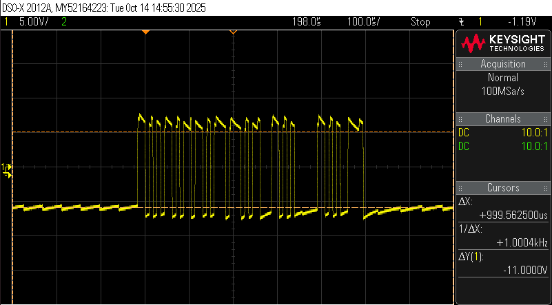
 

However, when I connect the MAX3232I to either the DC Power Supply or Electronic Load, the swing is much lower, peaking at barely above 0V and the signal appears much worse.  I had to set the trigger to <0V to even get the capture:

The devices are not responding to this command.  The actual swing from low to high *seems* like it clears 6V at the absolute peaks, but is well short on the lower pulses.

I figure this is almost certainly some kind of problem on the end of the devices I'm connected to, but I'm wondering if there are any suggestions as to what I could try on my end.  I have an email out to the manufacturer of the Supply and Electronic Load, to at least see if they will tell me what they have for their transceiver on the other end, but they have so far been unresponsive.  So here I am.  I've tried multiple different cables, and the Supply/Load respond perfectly when communicating w/ my PC over a serial terminal.  This makes me think in some way the transceivers are somehow out of spec with each other when I use the MAX3232I?

Any thoughts/suggestions appreciated.  Thanks!

  • This looks as if you have connected your TXD signal to the other device's TXD output (which tries to drive a negative signal).

  • Hi Clemens,

    This should not be the case.  The cable I am using is a straight (I.E. *not* a null-modem) cable (confirmed by continuity check on the pins).  This cable works for my PC to talk to both the equipment as well as the microcontroller individually, so TX should not be crossed on the controller.

    I can try swapping RX and TX anyway, but It'll be when I get back to my bench in a couple days.  Thanks for the input.

  • Hi Kyle,

    Do you have a schematic of the RS232 devices on both sides of the cable for the failure case? 

    Can you also probe the V+ pin during the failure to see if that pin is collapsing? 

    -Bobby

  • Please measure how that pin at the device behaves. An idle output drives to a negative voltage (like the MAX3232I signal). A receiver should look like a 5 kΩ resistor to ground.

  • Hi Bobby,

    I don't have a schematic for the test equipment side.  I requested one from the manufacturer but have not received any response yet.

    For my end, I am using a CY8CKIT-050 Eval Kit to attempt to talk to the equipment.  The schematic for the MAX3232I is below:


    I will probe to observe V+ when next I get the chance (within the week I should be able to get back to my bench to test)

  • Hi Kyle,

    From what I can see, the schematic doesn't have any major concerns. I would not recommend a 10 ohm resistor on R58 but if you are bypassing it with J37 then it shouldn't matter.

    Any thing else between the RS232 pins and the DB9 connector? (like TVS diodes?)

    You might need to probe the other board's DB9 connector pin 2/3 and see what voltage it reads. Like Clemens pointed out, we may be seeing contention if the other board's pinout is expecting a null cable instead of a pass through cable. We should be able to tell by probing pins 2/3 on their mating connector.

    -Bobby

  • Finally back at my bench today,  The suggestions that RX and TX needed to be swapped are correct.  I was not thinking about it correctly on my end.  If my PC using straight-through serial cable is able to talk to 2 different devices separately, it implies that their RX/TX are configured the same way on each of the devices (TX=Pin2 / RX=Pin3), requiring RX and TX to be crossed when the two devices want to talk with each other rather than the PC.

    When I swapped RX/TX between the microcontroller and the test equipment (putting RX/TX to null-modem configuration), I am getting responses to the controller from the power supply.

    Per usual, the fix is the simplest thing and that thing I thought I had ruled out.  All the help is appreciated regardless.

    Thanks!