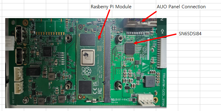
Other Parts Discussed in Thread: SN65DSI84
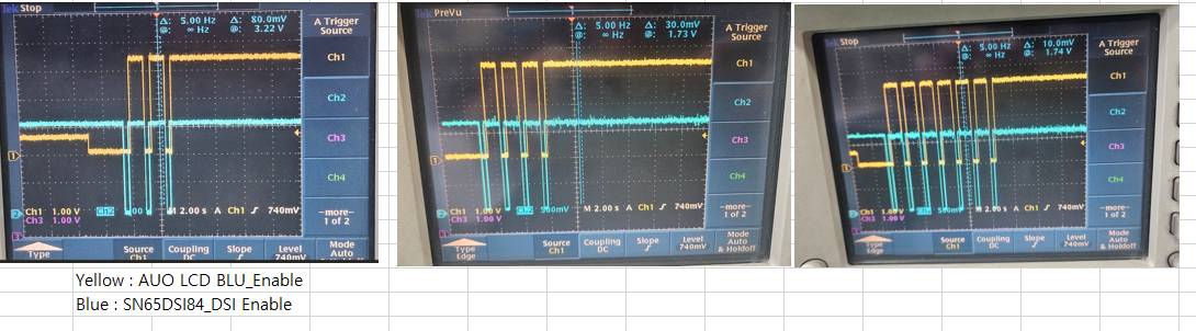
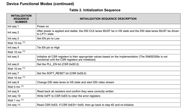
- Problem 1 : The LCD screen turns on normally, but then turns off and then turns on again when U12's 2Pin goes low.
- Problem 2 :
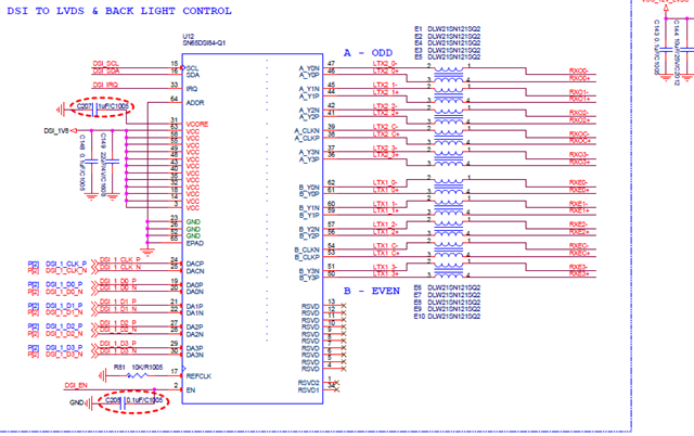
When I input 22.5MHz to a 37-inch LCD, the screen turns on (similar to Problem 1).When I input 45MHz to a 37-inch LCD, the screen doesn't turn on.3. signal sequenceRaspberry Pi(DSI) => TI SN65DSI84-Q1 (LVDS) => 37Inch LCD